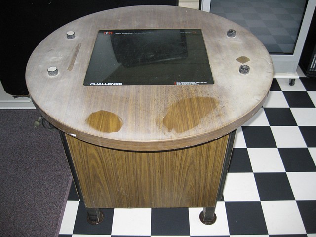
Mirco Challenge Cocktail, 1974
This is the earliest coin-op video game I've collected so far. It also predates all of the consoles and obviously, all the home computers as well.
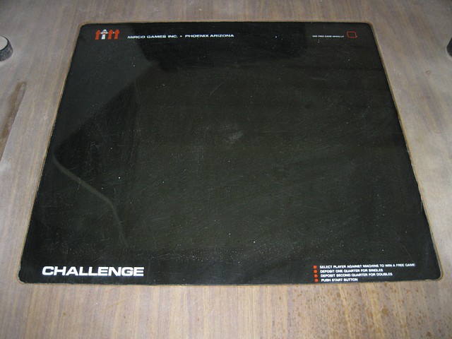
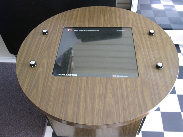
'Challenge' is a Pong clone for 1,2 or 4 players and was made by Mirco Games in Phoenix, Arizona in approx. 1974. At the height of their popularity Mirco set up an Australian subsidiary and produced (or at least assembled) the same machine locally in Artarmon, Sydney - the only obvious difference being the screening on the glass.
Now referred to as the 'Bronze Age of Videogames', the early to mid '70s machines were mainly Black and White units, some with colour screen overlays and using discrete logic components, prior to Microprocessors becoming commercially viable.
The market was initially dominated by 'Ball and Paddle' games led by Atari's 'Pong' and many copies by other companies, some with minor variations, such as this.
It intrigues me that Syzygy's (relatively) sophisticated space shooter 'Computer Space' released as early as 1971 did not capture the public imagination whereas Atari's (same people, new name) 1972 'Pong' was a huge success. I guess we all had to learn to walk before we could run...
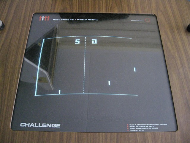
As purchased, this particular unit had apparently been sitting uncovered for decades, in the garage of a house with water views. As far as I can tell the white haze on the table is probably from the salty air. Seen here with a few test cleaning spots to find the best method for removing the haze.
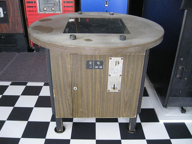
When powered on, it still shows the 'Attract Screen' with the ball bouncing around and the score displays are present but there are reportedly issues displaying the paddles and some of the controls are frozen after all this time being unused.
The coinmech is jammed, full of assorted denominations (presumably it is set for 20c coins) and as yet I don't have a key to open the door and clear it. I'm going to have a go at picking the lock rather than immediately resorting to drilling it out.
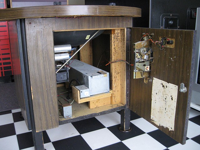
The lock isn't a high security model so picking it turns out to be easier and less messy than drilling. The machine obviously hasn't been opened in ages and needs a really good clean inside...
There's a popular legend that Atari engineers were called to repair their prototype Pong machine which had stopped working while being tested on location. Upon investigation, the engineer who attended found the machine had been so popular that the coin box had filled and coins had banked up, jamming the mechanism.
Well, my faint hopes that a similar situation might exist here were not realised but there was a good pocketful of 20c coins in the coin tray as well as a few ring-ins jammed in the mech. Finding any coins in the machine is always good and the same coins can be used over and over, to play the games in this collection.
Even better, there were enough 20c coins in the tray (just over 60) to estimate its last use. Coin dates ranged from 1966 (the start of Decimal Currency) to 1979 but nothing from the Eighties at all so the machine has probably been 'retired' for 40 years.
And while on the subject, I'll even hazard a guess why. There was some sticky tape residue, visible in the first photo on this page which was never cleaned off, just where you would place an 'Out of Order' sign. I suspect it developed a fault, was taken out of service and never used again. By 1979 or '80 it was already obsolete. Home systems were becoming common, offering paddle games and much more while new coin-op machines such as Space Invaders and Galaxian took the amusement industry by storm.
Having said that, the coin meter reads 17800 - assuming it started near zero when first used that translates to about $3500 which I imagine would have paid the machine off a few times over during its working life...

So, coining it up confirms there is an issue with the logic. 3 of the 4 paddles display OK though only one moves freely (Potentiometer problems most likely) but the left hand paddle is replaced by a solid wall (similar to the single player game but without the 'goal' area) making the left hand players invincible! I doubt a faulty control could cause that though one pot is very loose and might have a broken wire so I will check that first.
There is also no sound at all. That problem could be as simple as a faulty speaker or wiring but could equally be caused by a fault on the game board or in the audio amplifier.
I've replaced all four potentiometers and fitted new knobs, the nearest in size and style to the originals which I could find so far. I would have liked to retain the original knobs but the rim around the top edge was chipped on a couple of them, making them feel a bit jagged. Two were also missing their aluminium insert, the other two inserts were very corroded.
Having replaced the pots, all four controls now operate smoothly. The one which was loose (top left) did have a broken wire, this one corresponds to the second (inner left) paddle. There is still an issue with the outermost left paddle, with the new pot it now moves up and down but there is no space between it and the top boundary, only below so it appears more like a sliding door. In Player(s) versus machine mode the 'goal' area is still completely closed.
There's one more issue which I've noticed, when the first coin is inserted only the outer paddles should be displayed but both right hand paddles are present as well as the outer left one. Once a second coin is inserted the inner left paddle correctly appears.
Challenge (Pong Clone) PCB Repair
It's time to take the game board out, make up a test cable and troubleshoot the logic. I haven't been able to source a circuit diagram as yet so it looks like I'll have to do it the hard way, tracing from some known point such as the video output or control inputs and making a 'mudmap' as I go along. The other possibility is to probe each chip in turn using the relevant datasheets and look for irregular behaviour, missing or incorrect levels on inputs or outputs etc.
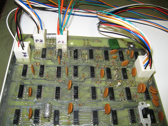
Making a bench test cable for the Mirco Challenge PCB is not as straightforward as I imagined - instead of an edge connector there are four PCB mounted multi-pin connectors with an unusual footprint, different to any Molex style connector I have seen. The Molex socket-pins which I have are also a larger diameter than the pins of the PCB plugs, making them a loose fit.
Edit: they appear to be "AMP Commercial Mate-N-Lok" type connectors but I haven't found a readily available local supply of them. For testing purposes I don't need the locking function - or the expense of specially ordering these from overseas.
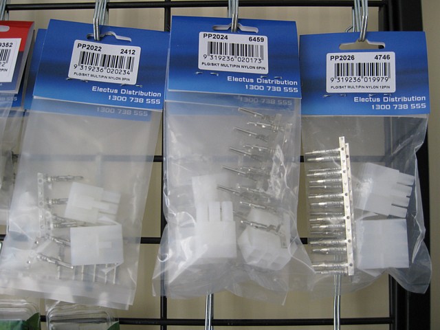
Fortunately I do have some other multi-pin plug and socket sets which I use to make up test leads, usually where there is no need to match up with an existing connector. Although the connector body doesn't match the Mirco's components, at least the socket-pins are a good fit for the PCB mounted plug-pins. These connectors are available from Jaycar stores in Australia or online. I'll need 23 socket-pins so 2 packs of the 12 way connector set (see photo, right) will be sufficient.
I could just use heatshrink tubing on each pin but then for testing would need to connect each wire to the PCB individually which is not ideal. Instead I think I can make up some new socket bodies with the 3D printer, to use with these pins. The tolerances are pretty tight as the pin spacing (pitch) of the PCB plugs is only 5mm. I'll have to make the pin receptacles narrower than the originals, still providing a groove for the locking barbs which retain the pins in place.
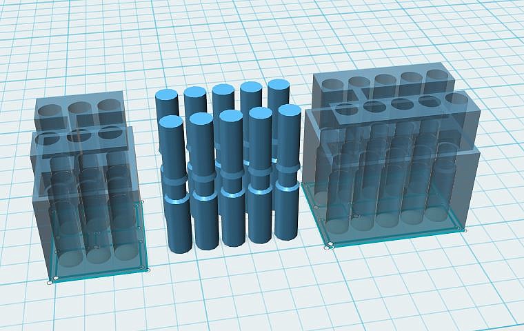
My 3D printer is set up for ABS filament and the narrow walls between the pins will test its capability. I had planned to print the sockets in colour-coded material but find that the 'natural' ABS filament without additional pigments flows a little better for very fine detail, with my 3D printer at least. These might print a little better with PLA filament and would be great using a laser type 3D printer.
The finished products can be seen here, connected to the Challenge PCB. Although there were a few imperfections in the 3D printed housings, in practice they work perfectly, retaining the pins and keeping them separated.
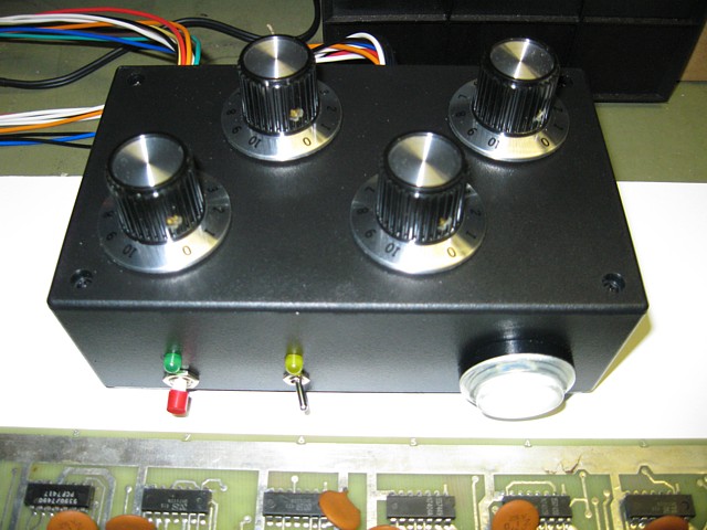
The test panel evolved into this full-function wired controller. All 4 Potentiometers are connected as well as the game select switch and start button. An illuminated Arcade button serves as the coin input - its Single Pole Double Throw microswitch is similar to the switch on a coin mechanism. The 'coin door illumination' supply from connector P4 is wired to its internal LED. The Green LED is connected to the 'Free Game' signal also on P4 while the Yellow LED indicates the 'coin counter' signal from P3.
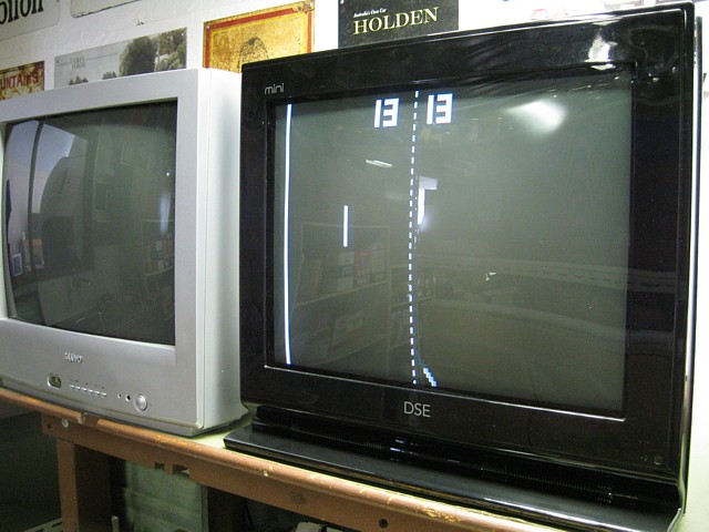
Connector P2 comes from the 5V power supply and also goes to the Audio / Video monitor. This Dick Smith Electronics late-model CRT TV (actually made by Konka) doesn't lend itself to RGB modification but can display Composite or Component video at 50 or 60Hz framerate - in this case Monochrome Composite video, 60Hz. Once the game is 'coined up' and started the audio blares from the TV speaker. At least that part of the game board works perfectly though there must be a fault within the audio amplifier or speaker wiring, in the Mirco cabinet.
The Mirco Challenge PCB has made its way onto my test bench so it's time to troubleshoot the two known issues. Firstly, the left most paddle positioning is working however the space above the paddle is displaying as a solid wall. Additionally when only one coin is inserted both right hand paddles are displayed - only the outermost paddles should be present in this situation.

I still haven't been able to source a circuit diagram for this PCB so we'll have to work it out as we go. Referring to documentation for the original PONG and other clones may help in a general sense however differences in the exact detail between systems can cause confusion so it may be best not to overload with irrelevant information.
A good start is to compile a PCB layout showing the component numbers and their locations. As there is no CPU the circuit functions are determined entirely by interconnection of the TTL logic components. The ICs are laid out on the PCB in a grid fashion. There is also a crystal at the 'top' end (row 1) while all 4 connectors for power, controls and outputs are at the 'bottom' end of the PCB. Based on that I'd assume repetitive functions such as sync generation occur near the top while interactive functions such as paddle positioning are handled closer to the inputs at the bottom end.
mirco.pdf Mirco Challenge PCB layout PDF document
mirco.ods Mirco Challenge PCB layout spreadsheet
Browsing some documentation for the original Atari Pong PCB, there were two 555 timer ICs which determined the 'vertical' delay from top of screen to the two paddles based on the position of their respective control potentiometers while another two '555's controlled the serve timing and the duration of the game 'score' sound.
The Mirco PCB has two 555 timers near the top end of the PCB which wouldn't be sufficient to control the position of 4 independant paddles anyway. Instead I'm assuming these are for the serve timing and sound duration as seen in the Atari example.
Right next to the P1 connector however there is a LM339A Quad Voltage Comparator which can be used to create the required 4 timing signals. After 'coining' the pcb up to display all four paddles as per the above picture, checking the LM339A's outputs with an oscilloscope confirms this as our starting point.
Each output of the LM339A is a rectangular wave whose mark / space ratio varies with movement of the corresponding player control. The transition point which varies will determine the vertical position, being the top of each paddle.
At this stage all four signals look correct so tracing from this point forward we can compare the working 'Player 2' circuit to the faulty 'Player 1' section and find the point where it goes wrong for Player 1, mapping the circuit out as we go. It's not necessary to check every pin of every IC along the way, if both signals are correct at the output of each stage we can move on to the next.
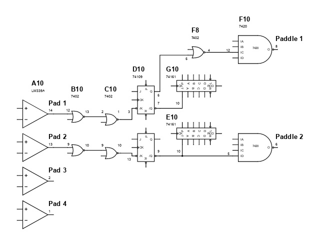
From the LM339A at location A10, both signals pass through two stages of 7402 NOR gates at B10 and C10 arriving at the 74109 J /K flip flop at D10. The inverted /Q outputs enable a pair of 74161 4 bit counters at G10 and E10. These counters would be clocked by a horizontal frequency signal, effectively counting the lines for which each paddle is active. The output data will also be used to determine the bounce angle of the ball, from horizontal for a collision at the centre of the paddle to sharply angled at either edge.
For the Player 2 circuit the /Q output also goes directly to a 7420 Dual 4 input NAND gate at location F10 whose output at pin 6 I've labelled 'Paddle 2'. It's a pulse which would correspond with the 'active' duration of the Player 2 paddle, shifting in time with movement of the Player 2 control input.
Assuming the other half of the 7402 at location F10 is for Player 1, I check the other output at pin 8 and it's all wrong. Checking its inputs, the signal arriving at pin 12 is noisy and low level, causing the incorrect output. Tracing back from there, it turns out instead of being directly connected from the 74109 at position D10, its non-inverted Q output travels through an additional 7402 NOR gate at location F8 which is faulty - with noisy non-TTL level signals on multiple pins.
So why the additional gate? I think it's used for the Player Vs Machine mode where the left hand paddle is replaced by a wall with a 'goal' area. In Player Vs Player mode the signal should pass through, albeit inverted which is why the non-inverting Q output from the 74109 is used instead of the inverted one.
Replacing the faulty 7402 at location F8 with a new 74LS02, also installing a socket - solves that problem. Surprisingly it has also solved the secondary problem where both right hand paddles (3 and 4) were appearing with a single coin input. It turns out that was caused by another gate in the same IC which should disable the paddle for Player 3 when only 1 coin has been inserted - its input on pin 12 going High, then Low again once a second coin is received.
That was a bonus, fixing both faults with a single IC replaced! If ever these two faults are observed on a Challenge PCB the 7402 at location F8 is almost certainly responsible - it is likely the only component which these two unrelated functions have in common.
After a bit of time to test out the repaired PCB I'll reinstall it in the machine and look into the lack of sound which is not a fault of the game board. It must be a speaker or wiring problem or a fault in the audio amplifier which is part of the monitor in this machine.
The only feature which I've been unable to test so far is the 'free game' awarded in Player Vs. Machine mode if the player(s) on the right hand side can score highly enough by deflecting the ball obliquely through the 'goal' area without missing the ball enough times to lose the game. So far, I've not had the reflexes or the patience to achieve that...
Ive reinstalled the Mirco challenge PCB into its cocktail cabinet and it's all working well. The lack of sound did turn out to be an open circuit (and very tattered) speaker which I've now replaced.
Unable to measure the original speaker's impedance, even after scraping the glue from the connecting wires running down the cone to take a measurment nearest the voice coil (so the coil itself must be open), I've referred to the monitor circuit diagram which shows the intended speaker impedance was 16 Ohms.
That's pretty uncommon now as most modern equipment (having fairly low voltage power supply rails), favour lower impedance 4 or 8 Ohm speakers to obtain a reasonable output power. But maximum output power isn't my objective, I want to ensure that the current draw on the amplifier output stage by the speaker doesn't exceed the original design expectation.
I also want to use a speaker with the same footprint, avoiding the need to drill new mounting holes in the base of the cabinet and the only speaker I had to hand of the correct size is 4 Ohms.
Being designed for use in a Pub, the sound level available originally must have been ear-splitting, given that the 'tones' generated by the machine are basically square waves, rounded only by the acoustic limitations of the speaker and cabinet. In my quiet and (normally) peaceful surroundings a tiny fraction of the maximum output power will be more than enough!
So the quick and easy solution is to add a 12 Ohm series resistor to the speaker. And in practice there's still plenty of volume in the 'Beep's and 'Boop's to satisfy the most hardened Pong fanatic...
Previously, I've replaced the potentiometer controls on the table and fitted four 'aftermarket' knobs as only two of the original knobs were complete and in good enough condition to use. I've been unable to find an exact match for the original knob so decided to attempt a 3D printed reproduction.
The finish of a 3D printed part isn't always good enough for 'cosmetic' items such as knobs but these ones are pretty straightforward and the original sides have a grooved appearance anyway so that will help to disguise the laminated layers of the 3D printed part. There is also an aluminium insert on top of the original which can be replicated, either in plastic or by cutting a piece of metal from a thin sheet and fitting it to the finished knob.
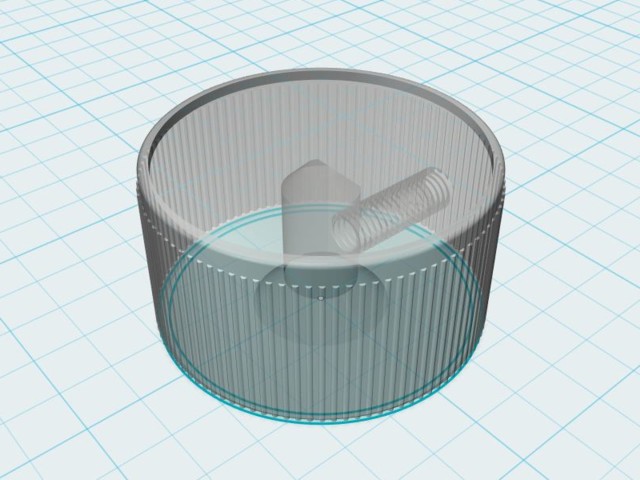
A 3D drawing of the reproduction knob showing internal detail. This part can be printed without any additional supports. The centre hole for the Pot. shaft has a flat side built into it and an M4 threaded hole for a retaining grub screw. The threads don't print perfectly but well enough for the grub screw to work, being all plastic it's important to avoid stripping the thread by over tightening.
My first attempt had an M5 threaded hole but this appeared too large so I have reduced it to M4. I already had some M4 grub screws on hand, these should be easily obtained from a nut and bolt supplier if required.
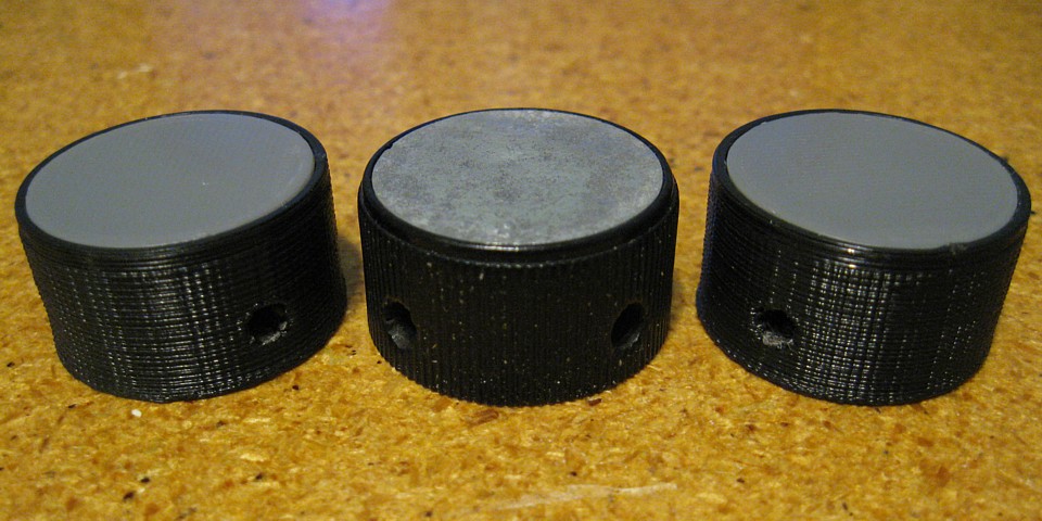
This photo shows two 3D printed knobs with 3D printed inserts and one of the original knobs for comparison. To achieve the smoothest finish on the inserts they have been printed separately rather than incorporating them into the knob and then fitted 'upside down', with the smoother side off the glass platform of the printer facing up.
The inserts could also be printed in PLA, with Aluminium and other metal effect filaments available. The knobs and inserts pictured have simply been printed in black and grey ABS material.
Although experiments with 3D printed replacement knobs for the Mirco Challenge were showing some promise, while my FFF Fused Filament Fabrication printer could produce a dimensionally accurate replacement the surface was not really smooth enough for a finished product.
Ideally, a laser / resin SLA printer would be the way to go for objects needing exact dimensions and smooth detail but in this instance there would still be the issue with then making perfect aluminium inserts to finish them off.
So what happened? It turns out my first assumption that I'd never find a correct replacement was wrong. While making up an order for other parts I stumbled across an almost identical knob right down to the knurling, two grub screw holes and no indicator line or marking, just like the original.
And here they are, right next to two originals and my 3D printed version on the right. When compared side by side they're just slightly taller but you'd never pick it on the machine, especially if a full set is fitted.
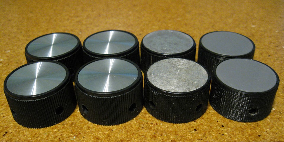
I ordered these in Australia from element14.com, part number 2057116 though they are available in the U.S. from ehcknobs.com, product code EH71-3N2S.
For such a simple game, Pong - and the Mirco Challenge are actually quite challenging, requiring quick reflexes and lots of concentration. The Mirco Challenge has the added feature of a single player game as well as 2 or 4 player vs player modes and even 2 players vs machine.
My Mirco Challenge PCB is back on the bench while I sort two new issues, the first was a limited range of movement of one of the paddles, caused by a faulty ceramic capacitor which measured about 20kOhms resistance (should read as an open circuit in a resistance measurement) on the input to the LM339A voltage comparator.
The second is unusual, although the collision detection is working and the game plays correctly sometimes there is no sound when the ball rebounds from the lower boundary. So I'm tracing back from the sound output to find the collision detection for the bottom boundary and then trying to see where the signal goes missing or is of marginal level.
I'm tracing back from the sound output at IC location G3 pin 8. The three inputs to this 7410 are the tones for collision with the bats (pin 9) Serve tone (pin 10) and top / bottom boundary (pin 11). So tracing back from pin 11 via ICs at locations G1 and E3 to F9 the collision detection for the bottom boundary appears on pin 3 of the 7400 IC at location F9.
Likewise, tracing back from pin 9 of IC G3 should eventually lead to the collision detection for the paddles. This method is time consuming and does require good note keeping to avoid confusion.
Here's a little update with the Mirco Challenge PCB repairs. The latest problem I've been working on was the occasional absence of a sound when the ball rebounds from the lower boundary. Interestingly the collision detection was working so the issue had to be somewhere between there and the sound output.
Tracing the circuit back I found the origin of the collision signal for the lower boundary at IC F9, a 7400. It was difficult to get a good look at the quality of the signal with my analog oscilloscope which has no storage ability, the signal not having a regular repetition rate. The levels looked OK though.
Following F9, 2 gates of IC E3, another 7400 forward the signal (combined with the top boundary collision) to G1, a 74109. Attempting to locate the exact point where the signal was being missed, only occasionally - while keeping the ball in play proved to be very time consuming and ultimately inconclusive so, taking a punt I decided to replace E3 with a 74LS00, also installing an IC socket.
Testing again, the lower boundary sound was still occasionally missing. This shifted my suspicion to IC F9 itself - even though the collision detection was working and the ball rebounding, by the time the pulse reached E3 at the other end of the PCB it was occasionally failing to trigger a sound via E3 and G1.
Perhaps the issue here was more to do with rise time than voltage level. In any case, replacing F9 with another 74LS00, installing an IC socket in this location as well, appears to have solved the problem and all the sounds now seem to be working correctly.
While I have the PCB on the bench it also seems like a good opportunity to try and trace the collision detection for the paddles, which is working perfectly on my PCB at present. This may be of some help to me or someone else down the track...
So here we go.. Because the collision triggers a sound we can once again trace back from the sound output at IC G3, a 7410. The paddle collision tone arrives at pin 9, this in turn comes from IC E2, a 7400. Its two inputs are the tone frequency on pin 2 and the collision signal on pin 1.
Tracing back from there we reach the other half of IC G1, a 74109, in this case pin 6 which is a Q output. Checking its inputs now I find the collision signal arriving on the preset input, pin 5. The incoming pulse length must be quite short as it doesn't show up clearly on my oscilloscope display but is detected by the trigger circuit. Switching to my cheap but funcional logic probe the signal shows up on the 'pulse' LED each time the ball strikes a paddle.
Now tracing back further via a 7404 inverter at IC D3, 7402 NOR gate at IC G2 all the way to a 7410 3 input NAND gate at location C9, this appears to be the origin of the collision detection between the ball and paddles.
When tracing a circuit back to its origin we must look for the output of a previous stage though we may also locate other inputs which are fed the same signal. If we trace back to an open collector output there is also the possibility that multiple open collector outputs could be connected (i.e.wire ANDed) together. In this case the combied signal would be the product of the first output AND the second output AND any others hence the term.
The 3 inputs to IC C9 appear to contain the position of ball and paddles, producing an output when the three inputs coincide, i.e. all are true. Of course if any of these 3 signals were missing there would be no collision detected but I suspect in that case the characters on screen would also be affected. If the paddles and ball are all present and correct but there is no collision detected my bet would be the 7410 at location C9 is at fault.
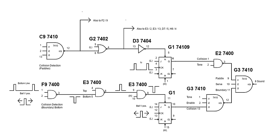
For each part of the PCB which I've worked on, I've sketched a diagram of the relevant parts of the circuit. Although far from complete the diagram is taking shape and may help with troubleshooting other PCBs with similar issues.
mirco2.pdf Mirco Challenge PCB partial schematic PDF document
Web Resources (External Links) -
The Arcade Flyer Archive - Video Game Flyers: Challenge, Mirco Games
Challenge (Mirco Games, 1974) Arcade Cocktail (German) - YouTube
The Golden Age Arcade Historian: Company Profile - Mirco Games
Challenge (Pong clone) Gameplay at Barcade Jersey City, NJ - YouTube
1974 Mirco Games Pong Arcade Cocktail table - YouTube
Atari PONG Rev. E Circuit Analysis and Lawn Tennis - Pong-Story.com
Video image positioning control system for amusement device - Google Patents
All images and text on this website are Copyright.
Contact: jbtech at telstra dot com