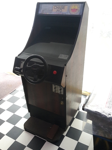
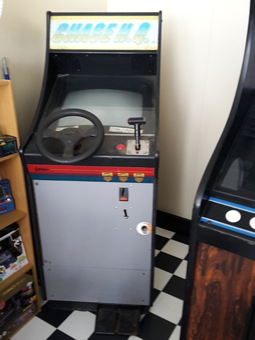
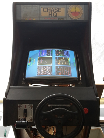
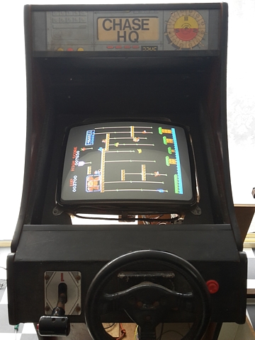
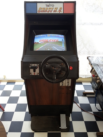
Chase H.Q. by Taito, Lowboy cabinet
I've a couple more Arcade machines for Repair, that's one out just recently and two in, putting a bit of pressure on Workshop space and prompting a Cabinet Reshuffle!
These ones are both Chase H.Q.s and must have originated as kits which were installed into locally made Lowboy cabinets. I've never seen Lowboys set up as driving cabinets before so these must be fairly uncommon. They most likely would have been operated in 'corner shop' settings rather than a full on arcade.
The initial objective here is to try and get at least one machine up and running, if both can be repaired that will be a bonus. I'll certainly be trying to avoid stripping either machine for parts, if possible.
Neither appears to be in good shape to begin with so we'll forego any attempts to power them on as they stand and skip directly to testing each major component in a more controlled environment.
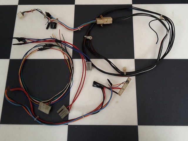
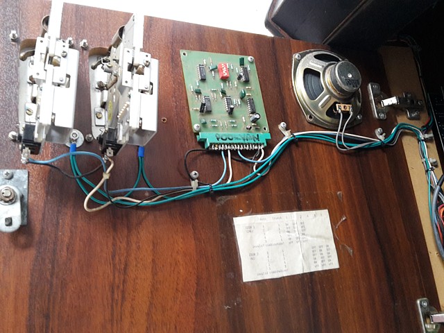
The steering, gear shift and pedals on both machines feel pretty worn and will definitely require overhaul, meanwhile a brief visual inspection inside each cabinet reveals one of the game PCBs looks pretty intact and wiring looks correct while the other had been hard-wired within the machine and since had those wires cut.
The assumption I'd draw from that is the wires were cut and PCB removed for repair when something went wrong then loosely placed back in-situ when it all became too hard. So that one will be the secondary, 'backup' unit and I'll begin by testing the better looking PCB from the woodgrain Lowboy cabinet.
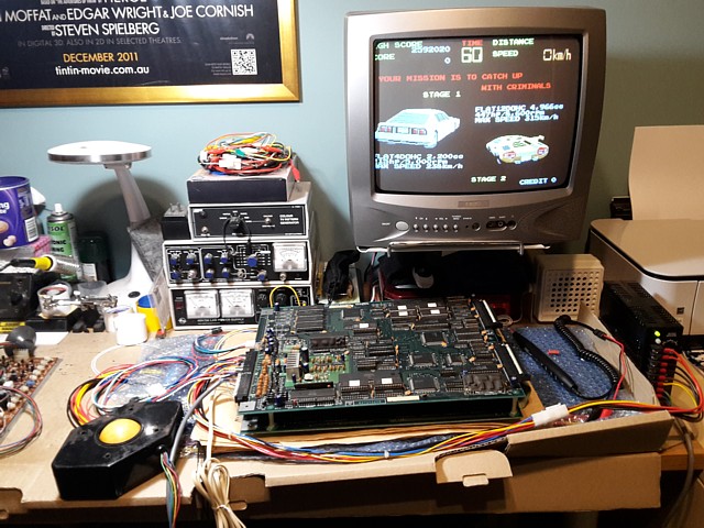
I've removed the first Chase H.Q. PCB set from its Lowboy driving cabinet to check it on the bench using my existing test lead with JAMMA standard power connections. The speaker pinout differs slightly from the JAMMA standard so I've added a new wire for that as well as making a separate RGBS monitor cable to suit the Chase H.Q. PCB.

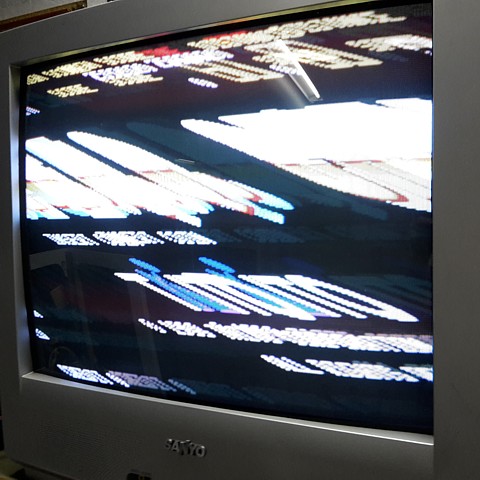
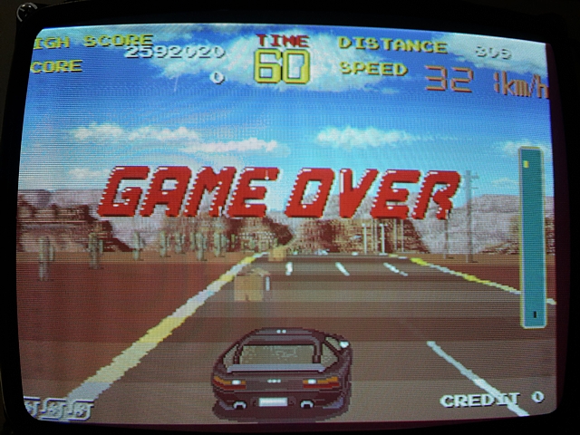
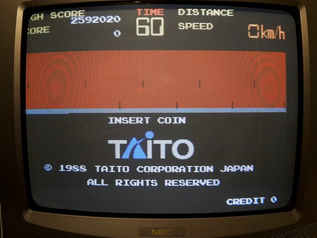
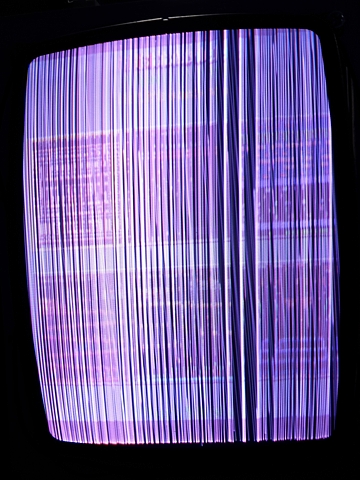
Powering it on, the signs are pretty promising with video being displayed but unfortunately the image is rolling, presumably lacking Sync. Using a wire link to add a credit and select Start, the game seems to be playing, with sound and Video which looks like it may be correct except for the absence of the Sync signal.
Looking at the circuit diagram for the CPU board, the Horizontal and Vertical sync signals are combined by IC 45, a 74LS86 Exclusive OR gate then output via a 100 Ohm 1/6W series resistor. This is a deliberately low power rating, no doubt chosen to act as a fuse in case of a monitor fault.
Upon checking, the sync signal is present at the output of IC45 but R27 does appear to be open circuit (Note to self: suspect monitor in machine, possible arcing problem!). As I'm currently running the PCB on the test bench with my own, RGB modded Sanyo TV monitor it should be fine to replace that resistor and continue testing.
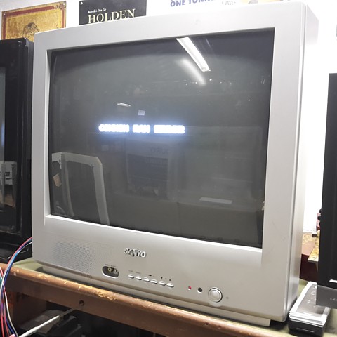
That gets the sync working but powering it on again there's some screen flickering followed by a COMMON RAM ERROR message. That's disappointing, it was beginning to look like being a simple PCB repair. I'm not sure why that RAM failed just at this moment but they do have a reputation for being unreliable.
The Common RAM comprises a pair of TMM2063 ICs and is shared by the two 68000 CPUs. The two processors interact by exchanging data in the common RAM area. I'm not sure which IC has failed but will try checking their inputs and outputs during initial RAM testing to hopefully identify the faulty one.
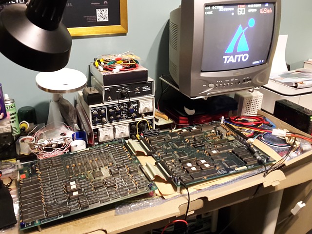
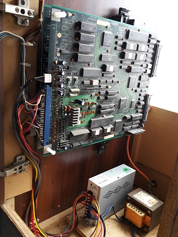
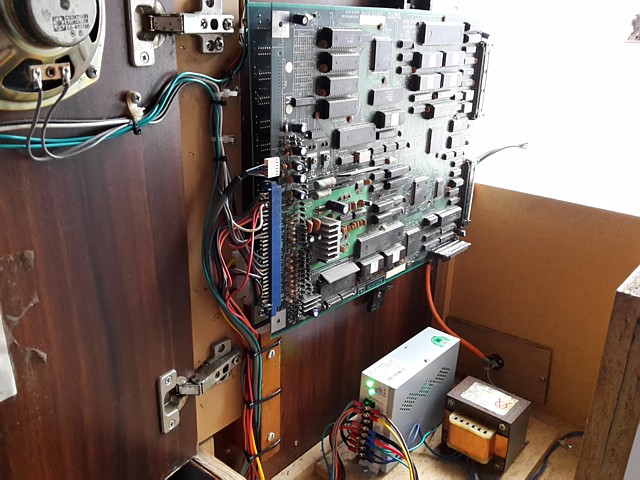
I don't have any TMM2063s in stock so will order a few and wait for them to arrive. Meanwhile I can proceed with testing the monitor, power supply and wiring within the Lowboy cabinet. Now that the game PCB has been removed it should be safe enough to power up the Lowboy cabinet and check those other major components without risking further damage.
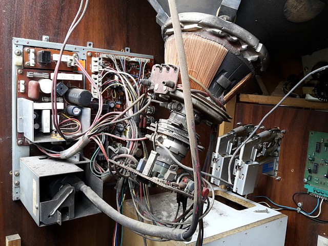
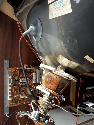
The first obvious sound when powered on is the noisy cabinet fan, then a steady 'Tic Tic' noise from the monitor chassis reveals an EHT discharge from the area around the flyback transformer. This would explain the blown resistor on the sync output of the game PCB, I notice the EHT wiring passes quite close to the Video signal cable.
A quick glance at the screen shows no obvious raster or image, in any case the chassis is faulty and needs repair - or replacement if parts for this model are unavailable. In the photo I've just unplugged the AC supply from the chassis so I can test the other items without the monitor running.
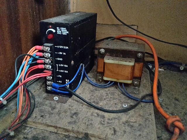
Now testing the power supply unit, all the outputs measure way too low, just a couple of Volts in each case. Even the red 'power on' LED is barely illuminating.
Although the supply is marked 220V near the AC input it's internally switchable for 110V or 220V operation. In this case it's connected via the 110V isolation / stepdown transformer so I've confirmed that the internal switch is correctly set for 110V operation.
The power supply unit could probably be fixed but to save time and improve reliability I have a brand new supply to install anyway.
I've been checking the component parts of the Chase H.Q. lowboy machine and so far I've found problems with the game PCB set, the CRT monitor and the DC Voltages from the arcade power supply. I haven't fully tested the controls but at first glance they seem worn and likely to need overhaul as well.
On the bright side the RAM ICs which I ordered to hopefully solve the latest fault on the CPU board have arrived. along with some suitable 28 pin 0.3" IC sockets.
As the Common RAM comprises two TMM2063 ICs I'd hoped to identify which one had failed but, checking the signals around them during the initial startup diagnostics I can't see any activity at all. It seems the RAM is tested and fails in an instant, after which there is no ongoing activity to view.
So, taking a 50/50 guess I replace IC 43 first. When that doesn't help I try its counterpart IC 44 and that one fixes the COMMON RAM ERROR. At least both ICs are socketed now which should make any future troubleshooting easier.
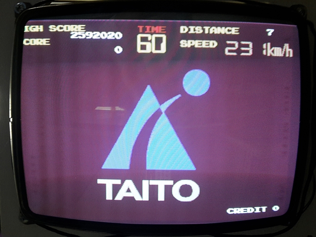
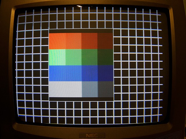
The PCBs are running again, this time with sync so we can have a proper look at the image using an arcade monitor from another machine which also happens to be on the test bench at the moment.
It's looking good but there's intermittently a slight fluctuation in the red level of the image, most noticeable when the attract mode cycles back to a black background.
That's most likely caused by a problem with the TC0070RGB custom module which comprises the Digital to Analog converters for the RGB signals. They're prone to failure and quite fragile, with luck it could just be a poor joint or broken pin which might be repairable otherwise it would need to be replaced.
Fortunately, reproduction modules are available if required.
I've made some progress with the Taito Chase H.Q. PCB set from the Lowboy machine, adding control inputs to my bench test lead also troubleshooting the incorrect levels of the red output signal from the game PCBs. In place of the steering assembly I've wired in one axis of a spare trackball while a single joystick allows input of throttle / brake, gear selection, nitro and 'steering wheel centre' signals.
This test setup is less than ideal as far as gameplay is concerned but does allow most of the game functions to be operated without resorting to a wire link, still used however for 'coining' the PCB up and starting the game.
After confirming the control inputs appear to be working correctly it's time to troubleshoot the incorrect and 'flickering' red output signal. Changing Dip Switch A No. 3 to ON prior to power on selects test mode which mainly comprises White text on a Black background. This is ideal for showing up the issue as all three colour signals should be the same.
Looking at the inputs of the TC0070RGB custom module with an oscilloscope the 5 bit data signals for each of the three colours appear much the same however the Red output signal never quite reaches zero or 'Black' level and can be seen to intermittently jump higher even where a background level should be displayed. This appears to confirm a component within the RGB module is at fault.
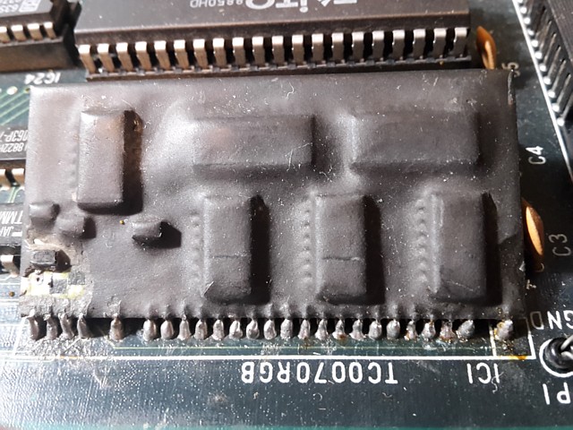
It seems the custom RGB module was a common point of failure on these PCBs. By the look of the soldering, this module has previously been replaced or broken pins repaired at some point.
There is also a small section of the resin which has been chipped off at the bottom left of photo which could have been an attempt to repair the existing module. That could also have been caused by an EHT arc from the monitor, travelling back along the video wiring to the module's RGB outputs.
The component which has been revealed is the transistor output buffer for the Red channel which makes it possible to check the signal at its base. Unfortunately the incorrect, fluctuating level is already present at this point so the fault must be prior to that, in the DAC circuitry within the module.
Although the outline of its components can easily be determined the chance of removing enough of the black 'potting' resin to replace any components without damaging the PCB tracks around it would be pretty slim. So replacing the module with a new reproduction part should be easier and more reliable than attempting to repair the existing one.
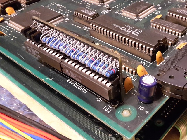
I've now replaced the Taito TC0070RGB custom module on the Chase H.Q. PCB set with a reproduction module, which has corrected the red intensity problem.
An original module would only have been available by robbing another Taito PCB from the era but fortunately reproduction modules have been designed and made to replace these obsolete components.
In fact, two alternatives exist. The first designed by Macro in 2014 reduces the component count of the original circuit by substituting a pair of GAL type Programmable Logic Devices and uses through hole components throughout.
A more recent reproduction by Caius in 2018 follows the original circuit, using surface mount components. The PCB is his own design but the module closely resembles the original in size and shape, thankfully without being encapsulated by the black 'potting' resin of the original.
Given my preference for through hole components over surface mount and the serviceability of the module itself, being repairable rather than 'replaceable' I've gone with the former. Both are excellent alternatives, each with their own advantages - the Caius reproduction being a ready made replacement part which is widely available, even listed on eBay at the time of writing.
Carefully removing the old module, some damage was evident between the PCB pads and adjoining tracks. Testing prior to soldering the reproduction module in place revealed a poor joint from the red output pin. This wasn't related to the previous fault but more likely wear and tear on the PCB, the module already having been replaced or joints repaired at some point.
The track width on these PCBs is really too narrow to reliably effect a concealed repair so I opted for a wire link on the underside of the PCB from that pin to a 'via' or plated-through hole along the same PCB track where the signal crosses from component side to solder side of the PCB on its way to the video output connector.
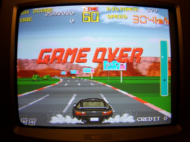
That done, the PCB set checked out fine, colours looking good in-game as well as the CRT test pattern in diagnostic mode.
It's been a while since I've made any significant progress with the first Chase H.Q repair, putting the game PCBs aside to concentrate on repairing some monitor chassis to go back into the machines. Having already repaired a number of faults on this PCB set I thought it was fully working but powering it up again on the test bench I've noticed a slight graphics issue.
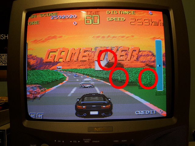
The imperfections in the image are not easily spotted during gameplay and have probably been present for some time just going unnoticed until now. They seem to affect the object layers and not the background, road, sprites or text layers. They're more noticeable in the tunnel scenes which have a plain texture and are also visible on the animated title graphics.
Interestingly, the defects don't move along with the objects but appear in regularly spaced fixed locations and just become more or less visible as the content changes. That would seem to suggest an issue with graphics RAM or memory mapping but the CPU board does run extensive memory tests on startup which all pass.
The Object ROMs and most of the object processing occur on the Video PCB so the first step is to set the PCBs up with that board accessible. I'm reluctant to simply turn the PCB set over due to a number of fragile components on the CPU PCB so I'll separate them and lay them out flat on the test bench, still connected by their ribbon cables.
I'm assuming the Object ROMs themselves (left of photo) are not the cause of the issue, a problem with these would cause an image defect which would move around with the objects as the layers were scrolled.
In the next row of ICs there is a single Sprite Map ROM which apparently combines the small graphic 'tiles' into larger ones so to eliminate that as an issue I'll try swapping that one with the same ROM from the second, currently non-working PCB set.
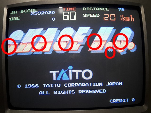
That causes a really interesting effect. The substitute ROM isn't working (actually it just needs its pins cleaned) and the moving objects are showing as solid blocks of colour. The original problem is still present but now much easier to observe against the plain backdrop.
So that was a fortunate discovery, sometimes worse is better. It's usually much harder to trace a subtle fault than an obvious one. I've ruled the Sprite Map ROM out as the source of the problem but I'll leave that socket empty for the moment as it will make it easier to diagnose the other issue.
Having said that I suspect it still won't be simple. I'll try and observe the 'glitch' using the oscilloscope then trace it back to its source if possible, starting at the Object bus where it leaves the video PCB.
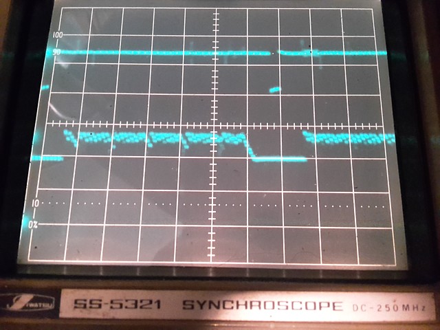
Setting up the analog oscilloscope now to use its delay trigger and second timebase to display a single line of video (one of the lines in the red block in the above photo which exhibits a number of black dropouts) our upper trace is the PCB's sync output. Triggering on this with high frequency reject to ignore horizontal sync we get a stable display with one vertical frame displayed and vertical sync visible to the right of the screen.
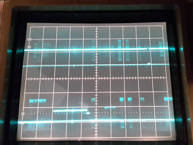
Our lower trace is the Red video output and we can see the red block in the first half of video frame which appears for a few seconds each time the attract mode cycles back to the beginning. Switching to display our A timebase intensified by the B timebase and adjusting the B delay and speed to highlight just a small portion of that red section approximately where the glitches are visible on the monitor, this can be seen as a bright patch on both traces about a third of the way across from left to right.
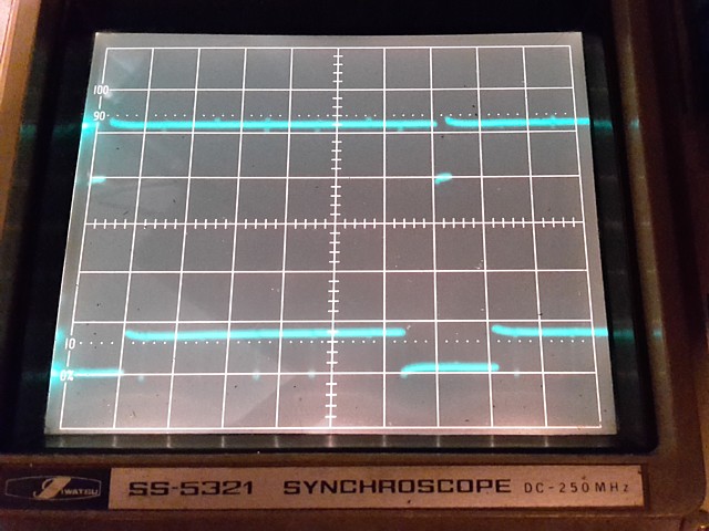
Now switching to display our B timebase, turning the brightness up we can see a single line of video with horizontal syncs visible in the upper trace. One line of (red) video is visible in the lower trace and we can see the dropouts on the waveform. There are five of these 'glitches' visible on the display but only three have been captured by the camera. We can now probe the Video PCB from the object bus outputs back, looking for glitches in the same positions.
So far we've been able to display the graphics 'glitches' at the final video output from the CPU PCB. Now we need to prove they are originating within the Video PCB and hopefully trace the problem back to its source.
Starting at the Object Bus outputs just before they leave the Video PCB via the 'F' ribbon cable towards the CPU PCB, the final stage is a bank of 13 x 74LS166 8 into 1 bit shift registers, each carrying one bit of the object data bus. Looking at each in turn, waiting for the attact mode to reach the same point eventually provides a result. Here, the 'gitches' can be clearly seen at the output of IC 149.
It could be the shift register itself is causing the issue or possibly the fault is in a previous stage. I don't have any 74LS166 ICs in stock so will order some just in case. Meanwhile I'll attempt to trace back further, viewing each input of IC 149 to see if the glitch is apparent as the data enters from the previous stage.
Continuing with the fault tracing on the Chase H.Q. Video PCB, to date I've observed a bit error on the output of shift register IC 149. Next I'll check each of its inputs to try and determine if the fault originates in a previous stage or if the shift register itself is the cause.
That provides a result of sorts, there is definitely a corresponding drop in Voltage on pin 2 coinciding with the output error but it's unclear whether the source of the signal is the cause or if the shift register is loading the signal when that particular input is selected. The signal in question is labeled FRDH2 which I presume refers to Frame Data.
Tracing that signal on the circuit diagram it appears to arrive from the previous stage via a 74LS374 buffer, the data then flowing into and out from RAM (IC75 in this case) and arriving at the input of the shift register IC 149. As the incoming data is buffered by IC 96 the fault must lie within this stage, narrowing the potential cause to those three components.
It's unlikely the 74LS374 buffer IC would be at fault, in most cases a faulty buffer will have outputs which are completely missing or continuously low level however being the most readily available and easily replaced it still seemed worthwhile to do so just in case, adding a socket in the process.
Having done that the fault remained unchanged, my suspicion now focused upon the 74LS166 shift register - the repetitive nature of the bit error seeming typical of a shift register fault. Unfortunately that guess was proved wrong as replacing that component (my parts order having duly arrived) also did not correct the fault.
That only leaves the possibility of a faulty RAM IC (so much for that extensive RAM testing on startup, obviously not as thorough as I imagined). I'd ordered a few spare CXK58256PM-10 RAM ICs just in case so, replacing IC75, installing a socket once again - here is the result:
The good news is the bit errors which were visible in the centre of the red area on the screenshot are gone. The bad news is bit errors in some other locations on screen including along the bottom of the red area are still there - why? Initially guessing a marginal component was on the threshold between working or not - after some thought I realised the problem was more straightforward, there were two faulty RAM ICs all along.
While this casualty rate seems pretty high, remember this PCB set was almost certainly affected by an EHT arc from the monitor so widespread damage was likely. Now to work out which other RAM IC must be faulty as there are 16 of these RAM ICs on the Video PCB and I only have a couple of spares...
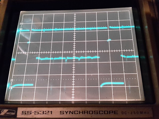
So, repeating the previous tracing procedure - first adjusting the B timebase delay on the oscilloscope to highlight the lines at the bottom of the red area with the remaining bit errors. Then, probing the outputs of the shift registers, IC 150 exhibits the corresponding errors on its output. Next probing each of its inputs, pin 4 appears to have a similar pattern of Voltage dropouts, corresponding to signal FRDF0. This in turn comes from RAM IC79.
Replacing IC79, adding a socket as always - cures the remaining bit errors. Reinstalling the Sprite Map ROM and testing, all functions now appear to be working correctly, at last. Time to complete the monitor chassis repairs and get this game back into the machine!
I've repaired the Chase H.Q. PCB set from this Lowboy driving machine as well as testing its monitor and power supply - both of those areas need work before the game can be reinstalled. So now I'll go through the rest of the machine wiring and electronics, beginning with the monitor.
When checked, there was some High Voltage arcing around the flyback transformer in the monitor chassis. It appears to be an older Kaga model and I'm pretty sure parts to repair it would be unavailable so the best option will be to find a suitable replacement.
Along with the two Chase H.Q. machines for repair there were a couple of spare CRTs and chassis in 'unknown' condition - that usually means they were removed from another machine at some point when they stopped working - but they may still be better prospects for repair so I'll check them out.

Checking each one in my monitor test setup and making up a list of issues, I've selected a slightly later model Kaga KZ-20EN chassis with a few problems to repair and overhaul. Once working, I've also routinely replaced the majority of electrolytic capacitors which should help to improve its stability and reliability longer term.
 |
 |
Trying it out in the lowboy cabinet, still using my test setup as a signal source there's another, not entirely unexpected issue. The old Chung-Wha CRT in the machine is worn out with poor focus, colour balance and tracking issues. These machines really had been run 'into the ground'.
Out it comes, to be replaced with one of the spares. This one is much better, a Mitsubishi CRT which would have originally been paired with the Kaga chassis as it also has a Kaga KZ-20EN label affixed.
 |
 |
Having removed the smoked glass to replace the CRT it's easier to see that there was no black mask around the tube at all. It wasn't quite so obvious with the glass fitted and the back on the machine but there would have been a mask present originally so I've found a spare one which will fit pretty well, with a little bit of trimming.
Moving on to the power supply and associated wiring, the supply originally fitted also measured bad with all Voltages too low. It may be repairable but as it was just a standard, generic arcade switchmode power supply the quicker, easier and most likely less expensive option is to replace it with a new unit.
That done, double checking the power supply wiring to the game PCB connectors - the Chase H.Q. PCB set has a 2 x 28 way edge connector which is pin compatible with JAMMA for the power connections at least, which looks OK - as well as a 12 pin Molex type header on the video PCB for power only.
That one was pretty messy, with power wires having been spliced onto a pre-used connector so I'd already ordered a couple of new Molex connectors and the correct crimp pins to replace that wiring from the power supply entirely.
There were also a few splices along the game PCB to monitor video wiring - Chase H.Q. uses a separate connector for the video, not the edge connector as per the JAMMA standard so the neatest solution was to make an entirely new cable from the game PCB to the monitor video input, once again removing the old spliced wiring.
 |
 |
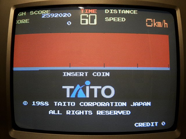
And with the messy and potentially unreliable wiring replaced, time to fire up the repaired Chase H.Q. game PCB set, back in its lowboy driving cabinet at last.
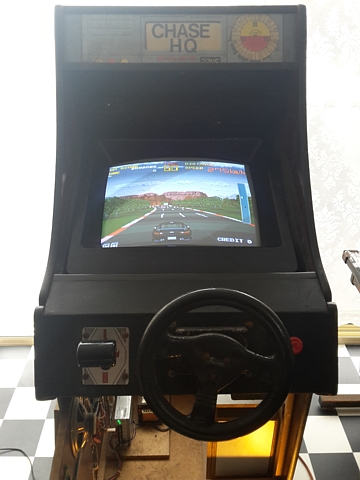
The first of two Chase H.Q. Lowboy machines is coming together after a lengthy process of repairing its component parts on the bench. Faulty Game PCB repaired, dead monitor replaced with a better model which I've also overhauled, Power Supply replaced with new unit, machine wiring tidied up and previously spliced sections replaced entirely.
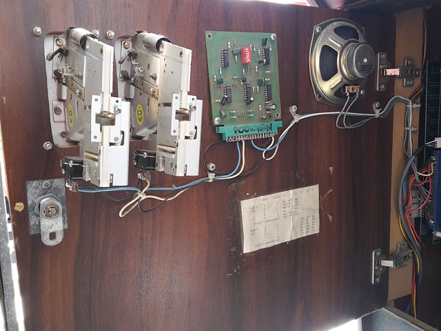
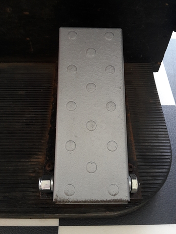
The game now runs in the machine, with sound. Coin mech switches, credit PCB and start button are all functional so the next components to check and repair are the driving controls, starting with the accelerator pedal.
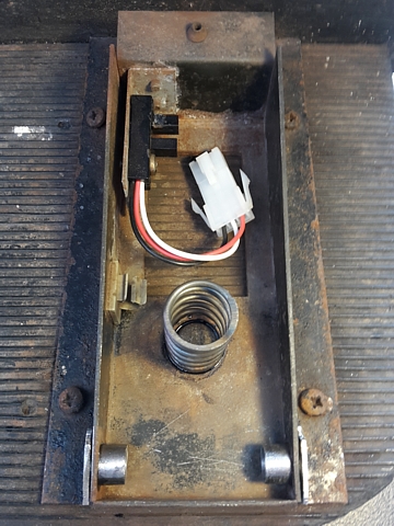
I'm beginning with the pedal assembly as there's an obvious problem. The pivot pin which was originally retained by a spring clip at both ends is loose and the pedal itself has come adrift. One of the shaft retaining spring clips is missing but the problem is more extensive than that as there is obvious wear and free play between the pedal, shaft and body of the pedal assembly.
Looking inside the housing, the wiring appeared as a birds nest with more splices and additional wires bundled up which appear to be for a brake pedal though none is fitted to this machine. Perhaps there was a two pedal unit fitted previously or planned for later addition but the gameplay really does not call for a brake pedal so I'll just remove all the spurious wiring and splices.
That reveals another problem. The pedal unit uses an optical sensor instead of a mechanical switch, the beam being cut by a tag on the underside of the pedal when operated. Unfortunately the photo interrupter body had been broken; there should be no contact between the pedal and sensor but the loose pedal had obviously collided with the plastic body of the optical sensor and broken it.
The photo interrupter sensor is a buffered type whose output is LOW when the beam from its IR LED is interrupted by the operation of the pedal. Unfortunately I haven't been able to source a replacement with the same dimensions and mounting arrangement so repairing the damage to the existing part seems the best option.
Fortunately the IR LED within the housing was not broken, its legs having been bent so I've carefully straightened them and repaired the broken housing with a bit of plastic welding, using some black ABS 3D printing filament and a soldering iron to fuse the plastic together. It's a little messy but seems quite strong, the part is well hidden inside the pedal unit anyway and will not be seen.
After removing all the splices and extra wiring the length of the remaining wires is now insufficient to reach the sensor so I'm adding a short lead and in-line connector in place of the original PCB mounted connector on the sensor body. That done and wires reconnected the sensor is working, all that remains is to repair the mechanical pedal pivot operation.
The body of the pedal unit and the pedal itself are both just made from folded sheet steel with the pivot shaft passing through. It appears there were plastic bushes in the pedal housing but these must have disintegrated at some point. I'd considered making some new bushes on the 3D printer but soon realised they would quickly suffer the same fate.
Although the original shaft was about 8mm in diameter the holes through the pedal, which had no bushes were worn with about a millimeter of free play. So to solve both problems I've increased the shaft diameter, substituting a 3/8" bolt and drilled the holes through the pedal to 9.5mm which provides a good sliding fit. I've also made up some new metal bushes which can be seen in the above photo.
The new bushes are made from a pair of 3/8" T nuts also drilled through to 9.5mm removing the internal thread and the flat portions trimmed to match the wedge shape of the pedal housing. The holes through the housing were also worn and irregular in shape, drilling these to 12mm allowed the new bushes to be installed with a bit of final fitting.
The pedal itself was originally chrome plated but the plating was completely worn from the top surface and the sides heavily pitted, the whole part being covered in surface rust. It could be bead blasted then re-chromed or powder coated and perhaps a pedal cover added to the top face but that is beyond the scope of this repair.
So for the moment a good brushing with a wire wheel on a drill and a quick coat of 'stop rust' type spray paint makes it a bit more presentable at least.
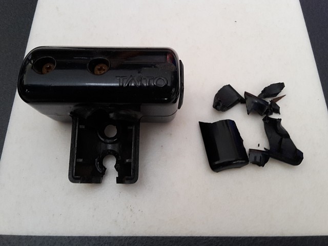
The next problem is with the gear shift assembly. Although working when tested the T shaped shift handle was loose and the button for Nitro Fuel or Turbo Boost (depending which version of the game instructions you read) was on the left side making it difficult to operate. As the gear shifter is fitted on the left side of the machine the button should be on its right side to allow it to be pressed easily with the thumb.
Unscrewing it to turn the housing around, the plastic which was already cracked, crumbled completely. The plastic must have weakened with age, that's a pity as it appeared to be a genuine Taito part with the logo incorporated into the moulding. So, to get this machine up and running I'll 'borrow' the gear handle from the other Chase H.Q. Lowboy machine (which is metal, not plastic) and source or make a replacement part for that machine later.
Fitting the replacement shift handle is straightforward but the result is not great, the metal T shaped part has a longer mounting stem so the shifter now extends further than the rim of the steering wheel and is too close for comfortable operation. It would be too difficult and messy to try and reposition either of the controls so a better compromise is to shorten the shaft of the gear shifter and then re drill and re tap the four 3mm mounting holes for the handle.
Pulling the button wires back temporarily I found another couple of splices (really!) so after cutting 35mm from the shaft and re drilling I fitted the replacement shift knob with its button, a short lead to pass through the centre of the shaft and another in line connector in place of the spliced wires. The result is much better, the controls now positioned well and fully functional.
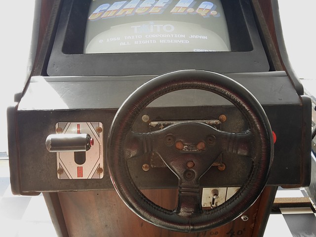
Continuing with the repairs and tidy up of the Chase H.Q. Lowboy machine, the accelerator and gear shift controls are now working. Surprisingly the steering control was working when tested so I won't be removing and overhauling that unit, being a repair project only and not a full restoration.
There were a number of different configurations of steering control for Chase H.Q, some with limited rotation and a potentiometer to register the wheel position. Others had 360 degree rotation and an additional sensor to reset the steering position each time it travelled through centre, some of those with a multi turn clock type spring to return the wheel to centre when released.
This one turns freely with no centering spring, if it originally had one it was probably long since broken and removed completely. The wheel does tend to turn back towards centre when released due to its weight balance, the centre spoke returning to the bottom of its arc.
In practice the game seems to recentre the steering at the beginning of each chase so doesn't tend to drive off to one side even if the wheel has not been centred exactly.
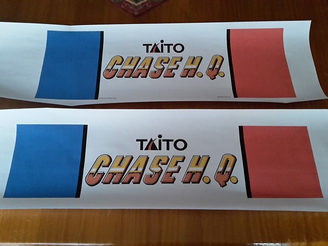
One cosmetic detail I will address is the awful marquee graphic which actually bears the LAI logo but this cabinet being an indeterminate make has a smaller marquee area so even that has been cut down to fit. I'll print up a couple of no frills marquee graphics to fit the two lowboy machines, each with slightly different dimensions.
The marquee in this cabinet is not illuminated but could be easily enough with a LED strip and some 12V DC wiring, The dedicated Taito machine also featured lights behind the coloured sections which flash during a chase sequence, I may look at implementing this also using LEDs if time permits.
There are two outputs on the Chase H.Q. PCB to activate these but when tested they only appear to turn the feature on, the flashing action must have been generated within the lamp driver board itself. Of course I don't have that and have not found any documentation however it wouldn't be too hard to knock up a simple circuit to drive a pair of LED lamps in a left - right and flashing sequence.
The new marquee looks much better and using an original style graphic seems fair as the machine does contain a genuine Taito Chase H.Q. PCB after all. In this picture I've trimmed the 'new' crt mask to sit at the correct level and added some black finished plywood strips to retain it in position as well as fill in the gaps around the top and sides, ready to refit the original smoked glass.
While I had the drop saw set up I've made a little shelf for the coin box to sit on - the cabinet has a slightly higher bottom panel, having been converted to a driving setup so the coin box was reduced in size to allow it to be lifted out. Adding a riser allows it to be drawn out without needing to lift it up. If the coin box was ever full of dollar coins this would have been quite heavy!
An important step is to check the external metal surfaces and controls are correctly connected to mains earth. In this case I've added wires from mains earth at the transformer to the frame ground at the switchmode power supply as well as the bodies of the coin mechanisms, steering, gear shift, accelerator pedal and the metal grill for the AC powered cooling fan on the back door.
Here you can see the Chase H.Q. PCB set barely fits in the lowboy cabinet and the PCB mounting bracket is closer to the rear, leaving the connector end without much support. I've added a piece of timber at this end with a ledge to support the PCB as well as some holes for cable ties to reduce strain on the cables and edge connector pins.
I've also put a 3 pin Molex connector in line for the back door fan to allow it to be disconnected when the back door is removed for maintenance. This is a lot safer than leaving the back door tethered by an electrical cable when opened.
Chase H.Q. - the mysterious flashing lights...
An additional feature of the Chase H.Q. PCB set is a pair of outputs to control two 'Patrol Lights', actually blue and red sections of the dedicated Taito machine's marquee graphic which flash during the chase segment within a game. I'm keen to implement the feature on this lowboy machine (which had no existing provision for marquee illumination) using some 12V LED lighting strips.
Looking at the circuit diagram for the Chase H.Q. CPU PCB it would appear that the PTR1 and PTR2 outputs were originally intended to drive 12V lamps directly with switching controlled by software. With this machine's PCB running on the test bench I checked the drive to these outputs using a logic probe and was surprised to find they did not pulse but remained on for the duration of the chase sequence.
This seemed to suggest an external flashing circuit with its own lamp driver which would make some of the hardware on the CPU PCB redundant. Searching online, I couldn't locate a circuit diagram for the flashing lamp driver board but did find some photos and references to the PCB which apparently drives three 110V incandescent globes as found in Taito U.S. dedicated upright machines.
The third globe driven by the circuit is the centre marquee light which is apparently turned off while the other two lamps flash alternately in a left - right 'wig wag' sequence. This is where I also found some conflicting information which suggested Chase H.Q lamps flashed together but at two different rates, about 2 and 4 flashes per second.
I now believe both versions were produced - the initial design apparently using CPU controlled switching of 12V gloves which was replaced in later machines (or perhaps for different regions) by an additional flashing lamp driver PCB which controlled 110V incandescent globes.
I don't have the flashing lamp driver PCB or even a circuit diagram for it and don't intend to use 110V globes anyway. As I'll be using 12V LED light strips I'd prefer to drive them directly from the CPU PCB. If that's not possible I could make up my own 12VDC version of the flashing lamp driver board.
So the observation that the lamp outputs on this PCB don't pulse but remain on during the chase segment would suggest this PCB was intended for use with the additional flashing lamp driver board - but there must be other Chase H.Q. ROMsets which support the CPU control of 12V lights.
How to confirm this, without burning complete sets of EPROMs to test? It seems the outputs are defined in MAME but not assigned to any actual devices, I've read descriptions of programs such as 'MAMEhooker' which can listen for occurrences of these outputs and assign them to actual lamps using interfaces such as 'LEDwiz'.
I'm just trying to implement the flashing lights on actual hardware so don't need to fully configure the interface for MAME but it will be helpful to observe the output behaviour using various Chase H.Q. ROMsets and choose one which will pulse the outputs during a chase, then work out which EPROMs need to be reprogrammed for this PCB.
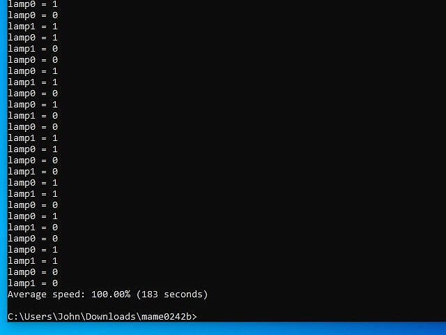
I've already verified the EPROMs fitted to the CPU PCB match the MAME 'chasehqj' (for Japan) ROMset - at least the program EPROMs match though graphics and speech are in English so some ROMs fitted to this PCB would not match the Japanese ROMset. So to begin with I'll run 'chasehqj' in MAME and direct any outputs to the terminal screen like so-

Here you can see both lamp outputs set to 1, which occurred at the beginning of the chase and then set to 0 once that stage was complete. Now repeating the test with the 'chasehq' (World) ROMset and the outputs continued to be set on and off, scrolling down the page from the beginning of the chase until the end of the stage as below:
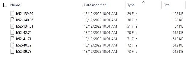
Now to work out which EPROMS would need to be swapped in order to effect this change. Of all the Chase H.Q. ROMs and EPROMs only the ones below are different between the 'Japan' and 'World' ROMsets. Of those, IC29 and IC36 are program ROMs for the main CPU and should be kept as a pair. The equivalent ROMs for the 'World' ROMset are B52-136 for IC29 and B52-130 for IC36.
So, guessing that the routines for the lamp flashing would be within the program and not contained in the graphics or sound resources I'll try substituting IC 29 and 36 from the 'World' ROMset, renaming them to take the place of files in the 'Japan' set. Apart from the expected checksum error on start the substituted ROM files appear to run correctly and lamp outputs toggle as expected.
The next step is to program a pair of 27C010 EPROMs for IC29 and IC36 using the Chase H.Q 'World' ROM files and try those in the actual game PCB set.
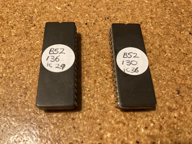
So, after replacing ICs 29 and 36 with the 'World' ROM versions I've connected a pair of 12V globes to the two PTR outputs using clip leads to see if they will now flash during a chase sequence. Disappointingly they behave as before, both turning on at the beginning of the chase and off again at the end.
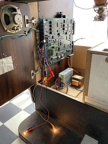
This is not as expected, perhaps there is some other variable which I hadn't considered. Comparing the DIP switch settings on the Chase H.Q. PCB to their virtual equivalents in MAME I notice one difference, the setting for the steering type.
There were two different types of steering control used in Chase H.Q. upright machines, the first having a 270 degree rotation with end stops and a potentiometer to sense the steering position. The other type had a full 360 degree rotation and used a spinner type bi-phase sensor (usually an opto - interrupter with a slotted disc and two sensors) and an additional sensor to set the position at straight ahead when the wheel was turned through centre.
This seemed to bear no relevance to the 'Patrol Light' behaviour but testing the DIP switch setting in MAME and then on the actual PCB confirms the CPU controlled flashing only occurs when the steering is set for the control with end stops. An external flashing lamp driver PCB must have been used whenever the 360 degree spinner type wheel was fitted.
So, mystery solved but that means I'll have to revert to plan B and make up a 12V version of the flashing lamp driver board to suit the LED strip lights.
The Chase H.Q. Lowboy machine repairs are pretty complete with all functions working except for the marquee illumination with flashing 'patrol light' sections, both features which were never originally fitted to this machine. In fact no provision was made for marquee wiring in this particular make of lowboy cabinet at all.
Fortunately the availability of efficient LED lighting strips makes it relatively easy to retro-fit the machine with a custom made marquee lighting setup with only low Voltage (12V DC) wiring required.
To implement the Patrol light flashing and centre marquee switching I've made up a simple circuit using a 556 dual timer IC with PNP and NPN darlington transistors to drive the 12V LED strips.

The circuit I've come up with is surprisingly much simpler than Taito's original flashing lamp driver which uses four ICs (as well as three triacs and opto isolators to drive the 110V AC globes) but the visual effect is the same.
I'd left space under and around the Darlington transistors to add heatsinks if required but as used here with the LED strips there is no need, after hours of testing they do not heat up significantly. In fact the Patrol Light sections, at only 150mA could in theory be driven directly by the 556 timer, omitting their driver transistors completely but I prefer the circuit to be over-rated and not stressed for long term reliability.
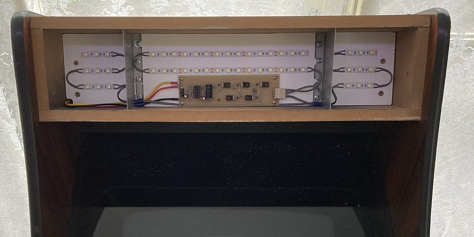
The LED strips are self adhesive and can be cut into multiples of 50mm sections, seen here affixed to some smooth melamine faced particle board which makes an ideal mounting surface. Including the driver PCB in the marquee area reduces the number of inter connecting wires required to three, +12V and ground for the LED current (only 500mA max or 6 Watts, when the centre section is lit) and the 12V 'PTR' control signal from the Chase H.Q. PCB, pin 22.
As there is no 'tunnel' between the marquee section and the main body of the machine with only the single walled back panel the wiring must be run externally or chased into the panel itself.
It would be possible to use a router to make a groove in the back panel, filling it in once the wires were run but for accessability I prefer to run them externally and conceal them by other means.
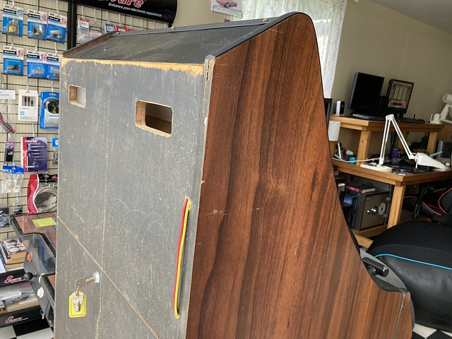
In this case I'll add some timber skids to the rear of the machine, routing a groove into the inside of one section to accommodate the wiring and allow future access if required.
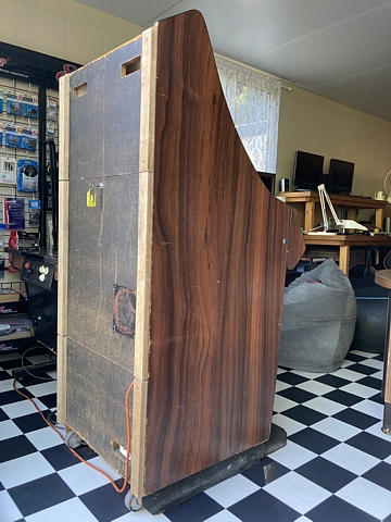
The skids are affixed with screws so can be removed for access or maintenance and I've countersunk them under flush so there's no danger of scraping during transport or if they are placed against a wall.
I've left the timber unfinished as there's a bit of cosmetic work yet to do on this machine but I'd probably finish them with Estapol, keeping the wood grain or they could be painted black along with the back panels which were originally black as you can see here.
That pretty well completes the repairs to the Chase H.Q. lowboy machine with a few upgrades along the way. It was a bit of a basket case but an interesting machine with obvious history of many years' operation on site somewhere and well worth saving in my opinion.
There's still plenty of room for improvement with some cosmetic restoration and maybe a full overhaul of the controls but is fully working once again. I've taken a short video of the retro fitted LED marquee and flashing Patrol Lights which can be seen in the YouTube clip below.
Web Resources (External Links) -
Chase H.Q. lowboy marquee lighting with flashing Patrol Lights - YouTube
The Arcade Flyer Archive - Video Game Flyers: Chase H.Q., Taito
Taito TC0070RGB Replacement - Macro's Arcade
Taito TC0070RGB Replacement - UK-VAC : UK Video Arcade Collectors Forum
Taito TC0070RGB Reproduction - JAMMArcade.net
All images and text on this website are Copyright.
Contact: jbtech at telstra dot com