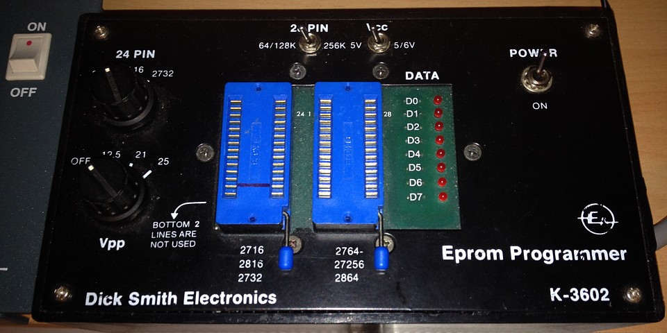
Dick Smith Eprom Programmer kit
I built this EPROM Programmer from a kit in the 1990s and it remained untested, in a box for over 20 years. At the time I bought it, much of the equipment I was working on had CPUs and firmware updates arrived in the form of a set of EPROMs which needed to be copied and installed into however many devices there were in service.
I had access to EPROM programmers elsewhere but it seemed worthwhile to set one up in my home workshop to save time. This one was controlled from a PC so ROM files could be stored on hard drive and a firmware library maintained. That feature seemed fairly advanced for the time as many EPROM programmers were standalone units requiring a master ROM to be read into memory before programming into other devices.
Only after buying the kit I discovered no real PC software was included. The enclosed design article provided listings of some example routines written in BASIC to control it via the PCs Parallel Printer Port (remember I bought it back then to save time, not to start a new hobby) otherwise there was a mailing address to contact the designer and purchase a copy of his own software package for the unit, which I did.
The software duly arrived but I had moved on to repairing other types of equipment and put it aside in case I needed it sometime. Only recently with a renewed interest in old hardware did such a need arise. The EPROM programmer and, amazingly, the floppy disc containing the purpose written software both having survived countless tidy-ups and even a move to new premises were both found intact and united at last.
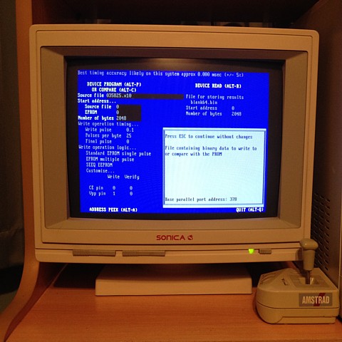
The software is DOS based so I'm using it with a Windows 98 system in DOS Mode. Windows 98SE is useful for running DOS applications and also supports USB drives which makes file transferring and backing up more convenient. The programmer works well but only supports EPROMS from 2k x 8 (2716) to 32k x 8 (27256). There is a mod available to support up to 512k bit (64k x 8) eproms but I haven't had a need to program those.
The software is quite flexible, for example I recently used it to read only 32 bytes from a (256 bit) PROM after making a little adaptor to the pinout of a 2716. Unfortunately, newer and larger EPROMS are beyond its ability with only a 28 pin DIP socket available so I can't use it to make a new boot rom for the Golden Tee PCB.
My PC controlled EPROM Programmer with its DOS based software has proved indispensable for programming and verifying EPROMS for early arcade games, particularly the 2716 (2k x 8 bit) type which requires a programming Voltage of 25V. It has also coped well with larger EPROMS up to 27C256 (32k x 8 bit), the highest capacity which the programmer was designed for at the time.
It might be possible to extend its range slightly with some modification to cope with 512k and Megabit (128k x 8 bit) types but its 28 pin socket would limit its expansion beyond that point. I've already encountered a need to program a 32 pin EPROM for my 2005 model Golden Tee Fore PCB so for later models such as this I've purchased the ubiquitous TL866 USB powered EPROM Programmer with its Windows based control software.
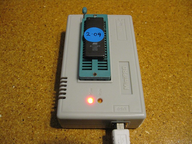
The TL866 has proved very capable for programming EPROMs from 2764 upwards and even GAL type programmable logic devices. It also has a very handy logic and memory IC testing utility.
Meanwhile my original programmer remains essential for 2716 EPROMs and has also been able to read and verify a variety of bipolar PROMs with the aid of some custom adaptors.
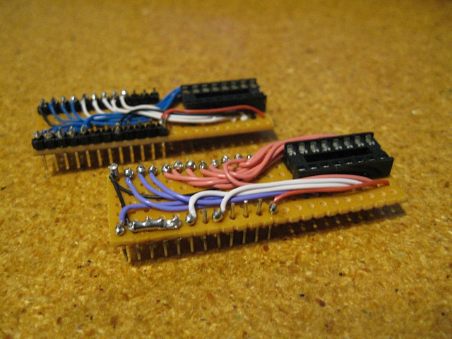
Above, a pair of adaptors for reading bipolar PROMs of 32 Byte and 256 x 4 bit capacity, converting their pin connections to the pinout of a 2716 EPROM. Below, a simple adaptor to tie one select line of a 9316 type 2k Byte PROM from a Space Invaders PCB to ground so it can be read as a 2716.
Having successfully read those devices the next challenge may be the ultimate one for this programmer; to read, verify and hopefully program the obsolete (and, frankly obstinate) 2708 EPROM.
Although once at the leading edge of technology the 2708 is now regarded as an archaic and often unreliable device which requires three separate power supply Voltages to operate in read mode as well as a high 26V pulsed signal for programming and a protocol unlike any later devices.
We'll attempt this challenge in stages, the easy part should be reading the EPROM. For this we just need to provide the two additional Voltages, -5 and +12 Volt. These could be furnished by a number of means, a standard arcade power supply could be used but is really overkill for the minimal current required.
The controlling PCs power supply module could be utilised, being a very early ATX unit -5V should be present as well as +12V but some custom cabling would be required to access this internal Voltage from the PC and run it to the extermal adaptor on the EPROM programmer, a bit messy for my liking.
Another option would be individual 5V and 12V DC plug pack type supplies, the positive side of the 5V supply connected to ground to create the -5V rail. That would be fine but doesn't seem to lend itself to the next stage which would be to come up with a 26V supply for programming.
A custom supply could be built of course but I'm looking for something simple for an adaptor which will be rarely used and then only for very brief periods. Reading a 2708 EPROM can be accomplished in seconds and programming within around two minutes. The simplest and most portable solution seems to be a bank of 9V batteries.
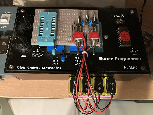
Three 9V batteries in series will give us -9V, +9V and +18V which can easily be regulated to -5, +5 and +12V. The +5V regulator is not required at this stage as the programmer already supplies this Voltage. Adding a fourth 9V battery will give us +27V which we can easily knock down with the forward Voltage drop of a diode or two to +26V.
We'll begin with a double pole switch followed by 7905 and 7812 regulator ICs for the -5 and +12V rails. A second switch will connect the battery for the +26V only when required for programming. This will save battery power without requiring the batteries to be unplugged between each read or write operation.
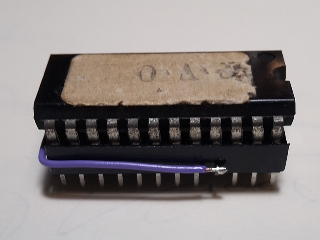
The pin connections for the 2708, 2716 and 2732 are the same except for pins 18 to 21 so the socket in the adaptor is wired 'pin for pin' with the 24 pin socket on the programmer but shifted across slightly to allow the tracks inbetween to be cut and alternate signals connected. To read the 2708 only pins 19 and 21 need to be altered, connected to the +12V and -5V supplies respectively.
Having done that and using the DOS control program to read 1024 bytes (1kByte) from each of the original Space Fever EPROMs, the resulting files all verify correctly with the known Space Fever 'old' version ROMset. The additional EPROM from the sound PCB reads as blank, I'm not sure if this IC is faulty so will be interested to see whether attempts to reprogram it are successful or not.
Programming the 2708 will be much more complicated than reading. In addition to the two extra power supply rails the /Chip Select / Write Enable pin 20 must be raised to +12V (I can use the programmers existing Vpp supply for this, set to 12.5V which is a little high but within the 2708s maximum ratings.) Once the address is selected and the data to be written is presented to the IC a 26V pulse of up to 1 millisecond duration must be applied to pin 18.
This is where the additional battery comes in. The programmer has the ability to provide a pulse of 5V only so that will be used to drive a BD678 PNP Darlington transistor connected to the battery powered +26V supply which will then be connected to pin 18. But it doesn't end there, each address must be programmed in sequence and the entire process then repeated for at least 100 passes (each address eventually receiving 100 or more pulses of up to 1 ms, totalling 100 milliseconds per address.
While the DOS control program is fairly flexible regarding number of bytes read, pulse duration etc. no provision was made for multiple loops of the entire address range. That particular software package is not open source so can not be altered to accommodate this requirement. The only option is to revert to the example control program written in BASIC and edit that to match the 2708 programming sequence. The existing DOS program can still be used for verifying and blank checking the EPROMs.
Components added to the adaptor for the 26V programming pulse. The +27V from the battery pack is connected via 3 diodes in series to provide a slight Voltage drop, each has a header pin so the Voltage can be checked with a multimeter prior to use and a wire link connected to the correct Voltage depending on battery condition. A little over 26V is ideal, allowing for some loss through the BD678 Darlington transistor.
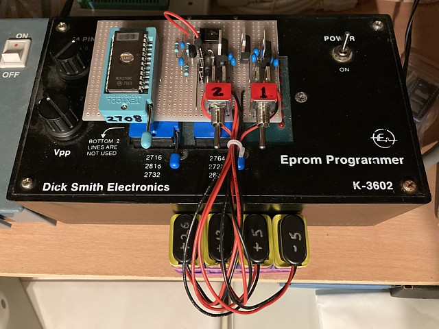
A positive going 5V programming pulse timed to 1 millisecond can be defined in software and is used to turn on a BC547 transistor which drives the BD678. A 10k Ohm resistor to ground ensures the 26V pulse returns to 0V when not active and this signal is wired to pin 18 of the adaptors 24 pin ZIF socket.
The design notes for the programmer included an example program written in BASIC which contained routines for blank checking and writing data to the EPROM as well as pulse timing. I've adapted these to reduce the pulse length to 1 millisecond as well as creating an outer program loop to provide the 100 programming passes. The readback feature which compared each byte just written to the original data can not be used for the 2708 so I've omitted that, the final result can be verified once the programming sequence is complete.
The minimum time required to program a 2708 EPROM would be 1 millisecond x 1024 Bytes x 100 passes plus some time inbetween each write operation to increment the address and place data, so around 2 minutes as a minimum. In the case of the BASIC program I've found it necessary to add a delay subroutine after each output to the parallel port, presumably my Pentium 3 computer is significantly faster than the 386 which the program was originally written for and without a delay the instructions are sent too rapidly for the parallel port to respond to each.
So without extensive trial and error testing I've just included a significant delay following each comamand sent to the programmer (retaining the 1 millisecond pulse duration of course) which increases the total programming time for each 2708 EPROM to almost 10 minutes, but after erasing the original data from the Space Fever EPROMs the adaptor has been able to successfully reprogram them to the High Splitter version.
As an experiment I'd call that a success! I've not only been able to read and verify the 2708 EPROMs but after erasing their original contents have managed to load a new file and replicated the necessary protocol for programming the EPROMs. I've also learned how the requirements for programming these devices are unique and why no later model programmers seemed to support them.
On the down side it's been a pretty fiddly process, first the new file must be loaded into PC RAM using the DEBUG command then the programming routine run in GWBASIC and finally the contents verified using the orginal DOS program. The other major issue is I'd greatly underestimated the drain on the 9V batteries which after just a few trial programming runs are already below their rated Voltage.
The issue with using batteries in series to create multiple Voltages is the ones at the bottom of the totem pole have to do the heavy lifting, the +9V one supplying current for the +5, +12 and +26V rails while the second battery provides current for the +12 and +26V. The 26V pulses seem to place a high demand on all three batteries on the positive side as each EPROM to be programmed requires 1024 pulses multiplied by 100 passes, so 102,400 26V pulses of 1 millisecond duration over about a 10 minute period.
So, a successful experiment but not a practical solution for programming multiple EPROMS. It could be developed further, perhaps revisiting other power supply arrangements and adjusting the delay timing but at this point I should mention I've also been working on a backup plan in case adapting the existing programmer did not work or proved impractical.
While reading up on the requirements for programming the 2708 EPROM I found an excellent solution already existed using an Arduino with a custom designed hardware interface and software by Matt Millman on Matts Tech Pages, link below. The open source hardware design and pre compiled software program having been very kindly shared by Matt, I set about ordering the components and a small batch of PCBs as well as a compatible Arduino device. The parts having duly arrived and following Matts perfect documention here is the result.
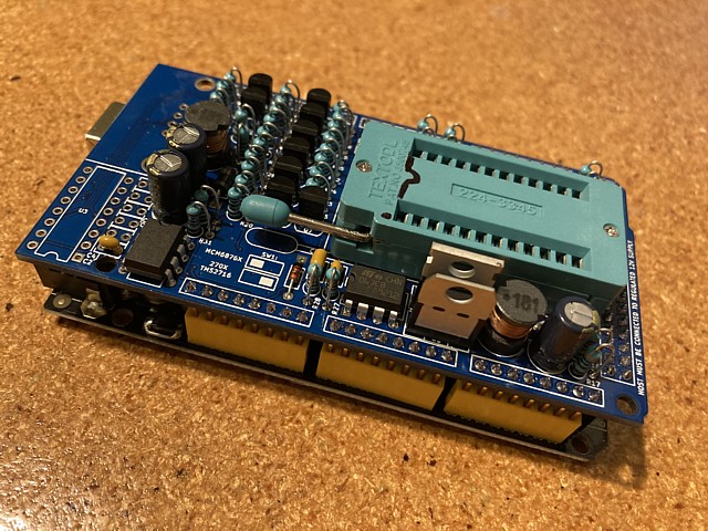
The design uses a 12V supply via the Arduino with a 5V regulator and DC-DC converters to generate the -5 and +26V supplies also required. The Windows program and USB interface easily handle the unique timing and multiple pass programming required and the few trial runs I have given it so far have been successful every time. My sincere thanks to Matt for sharing this brilliant solution.
footnote: Of all the 2708s tested so far, only the old Space Fever sound EPROM which read as blank failed to reprogram with both my adaptor and the Arduino based programmer so that IC is definitely faulty. The 2708 is well and truly obsolete and not easy to source in any quantity but a few old stock or second hand components are available on line so I'll order a couple and complete the Space Fever to High Splitter conversion when those arrive.
Web Resources (External Links) -
All images and text on this website are Copyright.
Contact: jbtech at telstra dot com