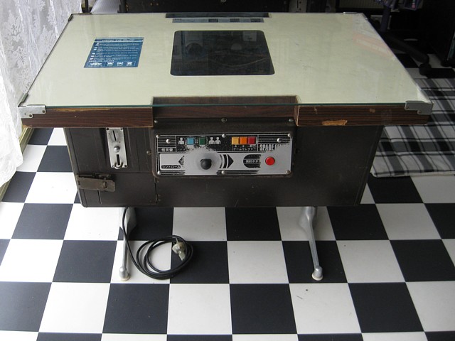
Space Fever (B&W) cocktail by Nintendo
First cab off the rank for my Arcade Machine Repairs is this Nintendo Space Fever B&W cocktail machine from 1979. It's a great candidate for repair and also for restoration as it's all there to begin with, it is significant and fairly rare as well. An Invader style game with some unique variations, even enhancements it's definitely not just a direct copy of Taito's Space Invaders.
It is a rather understated and largely forgotten page in Nintendos evolution, during the 'Invader Boom' in Japan sales of these machines probably helped Nintendo on their way to creating more ground breaking games such as Donkey Kong only 2 years later.
A lot of these machines were imported into Australia from Japan for a second run after their popularity there had peaked so there's probably more of them surviving here than anywhere else.
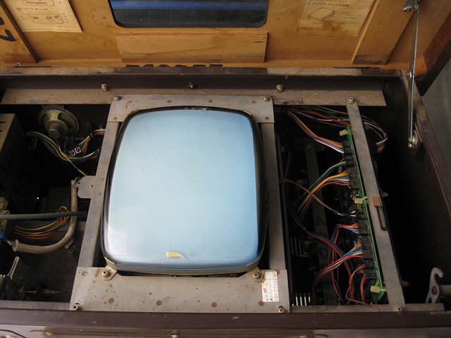
This one reportedly isn't running at all so the first step will be to check each major section; power supply and cabinet wiring, monitor, game PCB and see if each is working or not.
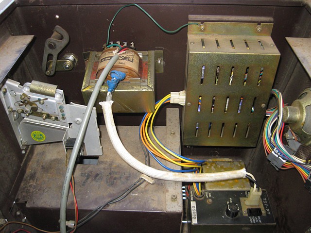
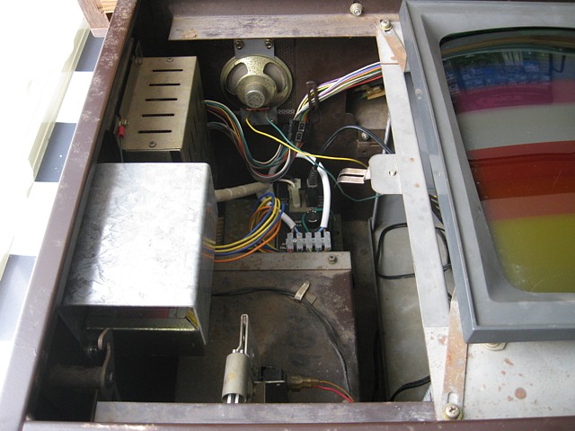
Beginning with a look inside to ensure nothing has come adrift it's nice to see the original power regulator is still present, many would have been replaced by now with a standard switchmode arcade power supply. A 100V stepdown transformer has been added to the power input wiring to suit our 240V mains. That needs a tidy up and some sort of shield added for electrical safety.
A new power switch has already been fitted, turning it on there's a faintly audible hum from the power supply but no sign of life from the monitor and no sound from the speaker. Operating the micro switch on the coin mechanism results in a click from the coin counter but no other sound or activity.
Trying the game start and controls now there's still no image on the monitor and no sound from the speaker, the sound amplifier is within the monitor so a monitor fault could cause the loss of both picture and sound.
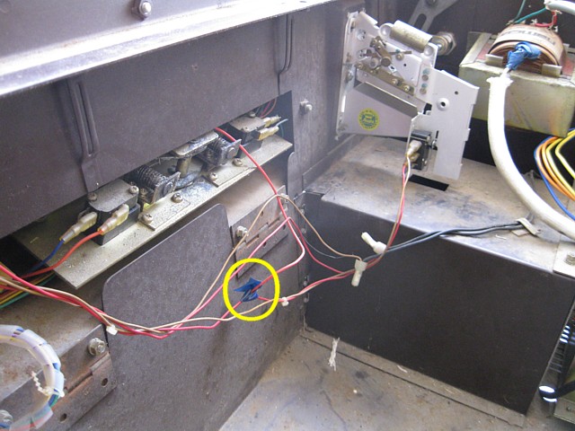
Interestingly, the 2 Player Start button also causes a click from the coin counter. Investigating, it turns out that button has been linked with a wire to the coin switch, making a rough and ready credit button. On the bright side, it didn't require any drilling or adding extra buttons to the machine but personally I'd remove the link and reinstate the coin mechanism which should be set for 20c coins.
Measuring the power supplies now, the +5V,+12V, -5V and +24V are all present at the game PCB connectors.The latter is apparently only used for the coin counter which seems strange as 12V coin counters were readily available and could have saved some extra circuitry. So at least the power supply is working though I'll still check it for swollen or leaky capacitors at some point, a common problem with these apparently.
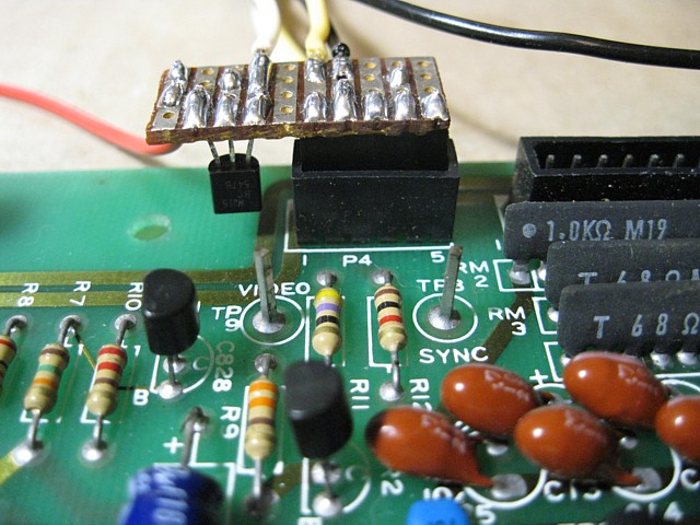
It's difficult to tell if the game PCB is completely dead as the monitor isn't working and even the sound is via the amplifier on the monitor chassis so I'll try it with an external monitor. The video is monochrome, seems to have separate sync and would be 60Hz but I'm not sure if the Video is standard or inverted and the Sync negative or positive. There doesn't seem to be any documentation available for the B&W version so I'll have to work out the details specific to this model as I go.
Making up a little video cable to try it with my RGB modified Sanyo TV using only the Green input and Sync there's no image on that monitor either. Looks like I'll have to make up a full test lead and troubleshoot the game PCB on the bench, also repairing the monitor separately.
So far I've tested the major parts of this Nintendo Space Fever (B&W) cocktail machine and it seems I need to repair the monitor as well as the game PCB also overhaul the power supply and tidy up the wiring.
The original monitor actually uses an AV modded Black and White TV chassis, complete with no longer required IF stage inside a metal shield and a combined power switch and volume control. Tracing the input voltage it turns out that power switch has failed. Fortunately it is not required as the machine's main power switch is used to turn the monitor on or off, along with the power to the game PCB. To correct the fault I simply bypass the switch with a wire link on the solder side of the chassis PCB.
That gets the monitor running with a faint raster but looking closely at the PCB many of the electrolytic capacitors have a residue from some leakage around them. To be safe I've decided to make up a list, order and replace most of the electrolytics on this PCB using slightly increased Voltage and temperature ratings where possible to ensure longevity also cleaning up the residue in the process.
Having done all that and using my usual test setup which supplies a RGBs signal from a multigame PCB, in this case only using the Green and Sync signals there is an image but the monitor appears to require a positive going sync signal while the test setup provides a more commonly used negative sync. As a result the image is shifted and the clamping circuit is not functioning correctly, the picture being washed out with retrace lines visible.
I could make up an inverter for the sync signal from my test setup using a transistor but think I'll just put the monitor back in the machine until I've finished repairing the original game PCB which will provide the required positive sync signal. One final test before removing the game PCB and the monitor shows a good raster without the retrace lines, the game board may be outputting sync but definitely no video at this stage.
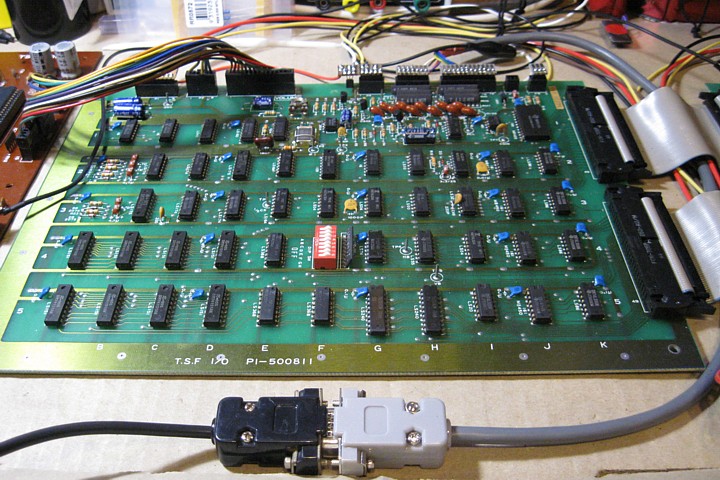
I've made some progress with the Nintendo Space Fever repairs, the Black and White monitor is up and running and now I'm setting up the game PCB to troubleshoot and repair on the test bench. I don't have the exact connectors to match the ones used on the Nintendo PCB but do have some Single in Line sockets with the correct pitch which will do. They don't incorporate the locking function but that is not required for a test setup anyway.
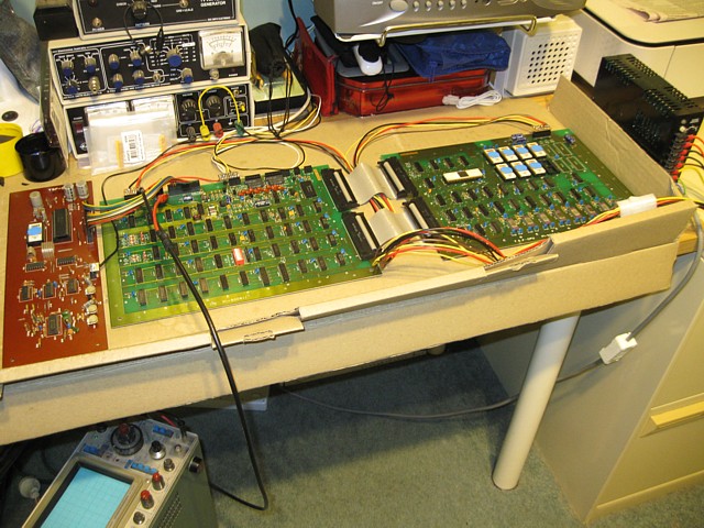
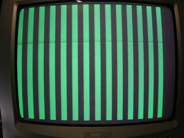
Using my standard arcade PSU I've connected all the Voltges to the required pins on the CPU and I/O boards except for the +24V which isn't required, only being used for the machine's coin counter. I don't have the extra space on my test bench for the original Black and White monitor so I'll be using my RGB modded NEC TV, adding a transistor inverter to the sync output from the I/O PCB and sending the Monochrome video to the Green input only.
Next the low level audio from the sound PCB goes to an RCA connector which plugs into the NEC TVs audio input. Having done all that and powering the PCB up I get - nothing. There's no Sync or Video from the PCB, quickly checking the supplies are present then the clock signal test points on the I/O PCB, these confirm that the main crystal oscillator isn't running.
Powering it off again, a closer visual inspection reveals one of the pins from the 20.160 MHz crystal has broken, right where it emerges from the package and not leaving enough of a stub to solder on to. It's a common problem, the legs are often brittle and prone to corrosion. What's not common, unfortunately is the crystal frequency. 20.160 MHz doesn't seem to be a commonly used frequency and I haven't been able to find an exact replacement.
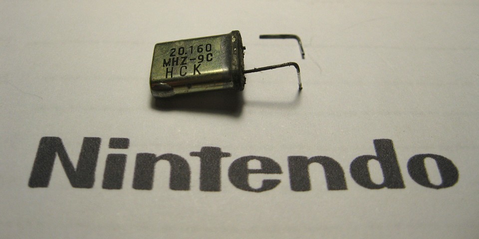
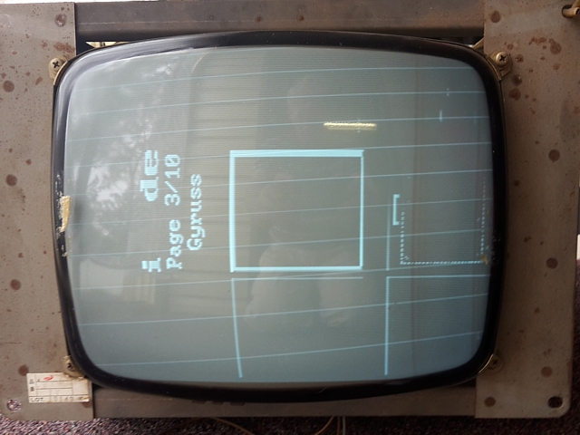
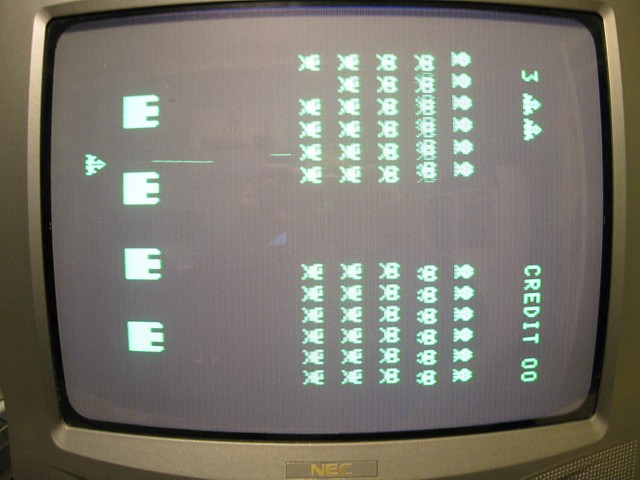
I do have some readily available 20MHz crystals though, which are only about 0.8% lower in frequency and I can't imagine any real problems or noticeable difference so I'll try one of those. That gets the clock running, sync from the I/O PCB and even some video so let's have a look:
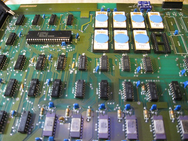
Hmmm - not great but better than nothing. There's no movement, if the power is cycled sometimes there is some random 'garbage' added to the image, possibly just the contents of the RAM at power on. I'll start with a look at the signals around the CPU to see if it is attempting to run. At this stage I would usually remove and verify the EPROMs but as these ceramic package ICs have notoriously fragile pins I don't want to risk breaking any, I'll try to diagnose the problems in-situ first.
Checking all of the signals around the 8080A CPU, power supply rails and ground are correct, clock inputs; 12V signals at approx 2MHz both present. The RESET line (active High) is Low so that is correct. Control signals, address and data lines are all active but not as you would expect for a running program - the waveforms are all very repetitive as if the program is stuck in some sort of a reset loop.
Looking further to try and find the reason for that, all of the 4116 RAM ICs have signals on their address inputs, data inputs and outputs so no obvious problem there. Checking the EPROMs, all have signals present but some of the address lines are barely active which seems wrong, they all appeared more 'normal' at the CPU end. Looking at the circuit diagram, the address lines are buffered by some 74LS08 AND gates before arriving at the bank of EPROMs so I'll check those next.
When I check the signals at the 74LS08 ICs it seems some of the logic levels arriving at their inputs are wrong, resulting in the loss of some of the address activity on their outputs. So the fault is not the AND gates themselves, rather a poor connection between the CPU and their inputs, most likely caused by a bad CPU socket or corroded pins. I'll have to remove the CPU from its socket to have a look.
As these PCBs were installed in the machine, mounted to a vertical surface one side of the CPU faced 'down' and was fairly unaffected by dirt or moisture settling on its pins. That side looks pretty good..
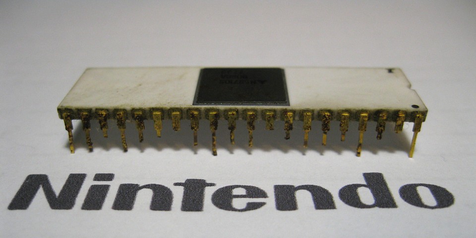
Unfortunately, the other side which faced 'up' was very corroded with a number of pins so badly deteriorated they just broke off and remained in the socket. So the CPU and its socket both need replacement.
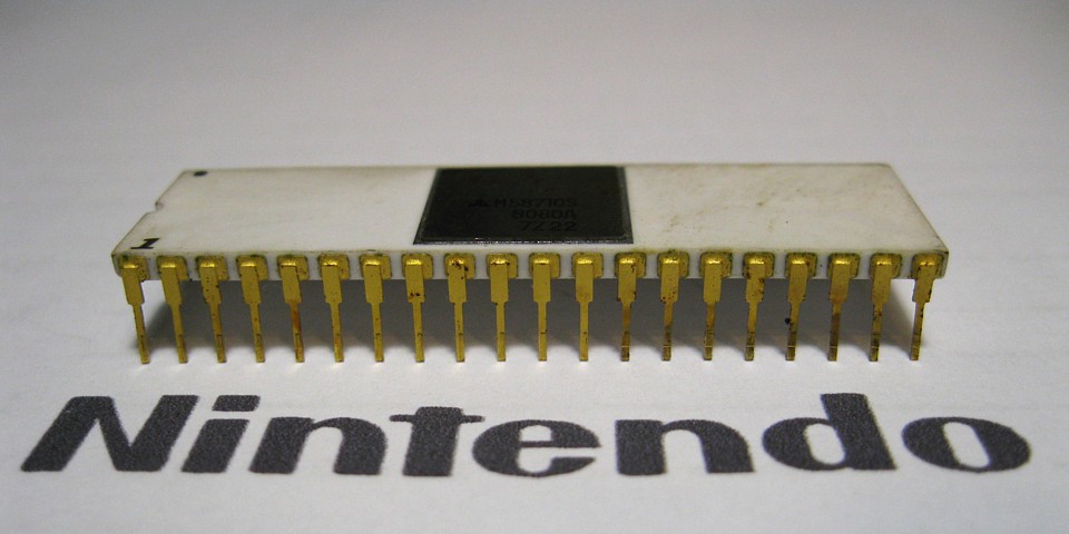
As luck would have it, I do have an 8080A CPU in stock as well as some 40 pin IC sockets. The CPU isn't spare exactly, I've been keeping it to repair one of my own projects but I can use it here and try to order a replacement to fix my 'Shuttle Invader' PCB later.
Replacing the socket and installing the 'new' CPU (made in 1979 according to the date code on the IC) the game is now up and running, fantastic! There seem to be a few issues still to solve, some of the sounds appear to be missing so I'll check those next.
Repairs to the Nintendo Space Fever Cocktail have been progressing well, better than most of my own projects it seems! The Black and White monitor is running, waiting for the game PCB to be refitted for final test. The game PCB is also running now except for a few of the sounds which are missing.
With the PCB set on the test bench, so far I've replaced the CPU as well as the crystal on the I/O PCB, both had failed due to corrosion. Fortunately as most of the ICs are oriented the other way their legs seem to be less affected than those on the 'high' side of the CPU or the crystal whose leads were also facing upwards and prone to dirt and moisture settling on them.
I've also placed labels over the glass 'windows' on all of the EPROMs, although they are not easily erased by sunlight alone (I did try that once as an experiment) sitting around for decades with the machine open might pose some risk to their contents, who knows? For my own peace of mind I've covered them anyway.
To fully test the game operation I've added connections to the player 1 and 2 controls, from a DB9 connector to suit my Quickshot joystick. To test both sets of controls independantly without needing a second cable I've wired Left, Right and Button 1 to Player 1 inputs with Up, Down and Button 2 connected to Player 2, just using a wire link for coin input, start and game select inputs.
Having done that, everything is working well apart from the few missing sounds.
The Sound PCB has two main sections, firstly an 8035 Microcontroller with 2708 EPROM which provides all of the musical tunes, Invader marching tones and UFO Flying / hit sounds. This is working while the other section uses a SN76477N complex sound generator to create the shots, Invader hit and Laser Base explosion sounds. These sound effects are all presently missing.
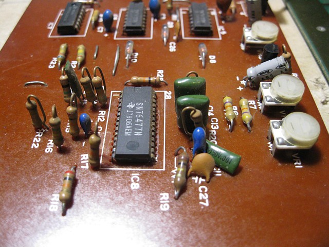
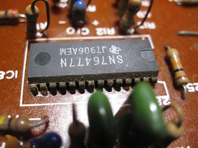
The SN76477 sound generator was produced in two package sizes, a standard 28 pin DIP and the smaller SDIP form as used here which has about 2/3 the footprint of the regular DIP outline. Checking the supply rails and the logic ICs before the sound generator, all look OK so the sound IC must be faulty. Once again its pins on the right hand side which face up when installed in the machine are very rusty so I imagine this would be the cause.
I don't have a spare one in stock, there are some on other boards I have but 'borrowing' one of those would be a last resort due to the extra time and risk of damaging one in the process of desoldering and reinstalling. Instead I'll order a 'new' one (probably still reclaimed from old PCBs I expect) and hope it arrives without undue delay.
Meanwhile I'll put the board aside and give that Power Regulator module an overhaul. There's no point returning the repaired game PCB to the machine if the power module is just about to fail so it's worth doing a bit of preventative maintenance.
The Nintendo Space Fever cocktail machine I've been working on had multiple faults to begin with so I've been checking and repairing each major section separately to address one issue at a time.
The Black and White monitor is up and running now, the game PCB set is also working except for a few missing sounds. I'm waiting on an IC to complete that repair so in the meantime I'll finish off the Power Supply and cabinet wiring.
The power regulator module was working when tested but these units are known for deteriorating and leaking capacitors so I'll try to extend its working life by replacing those critical components before they completely fail.
Opening the module up, the PCB is pretty crowded which doesn't help heat-wise. There are a few capacitors which have leaked some of their electrolyte onto the PCB which needs to be cleaned off and some which are discoloured due to being located a bit too close to heatsinks. Electrolytic capacitors don't heat up by themselves in normal operation but are affected by heat from other sources on the PCB such as power transistors, resistors and ICs.
I'll replace the full set using a higher temperature rating, 105 Deg. instead of 85 Deg. also going for a slightly higher Voltage rating wherever possible to be on the safe side. As an added benefit the new capacitors are all slightly smaller than the originals they are replacing, providing a little more air space around them which will reduce their exposure to heat sources.
Having done that, reassembling and re-testing all the Voltages look correct. Next issue to sort is the mains wiring. When the machine was converted to run on our 240V mains a stepdown transformer was added between the mains input and the original 100V cabinet wiring. Although this did work the stepdown transformer was neither fused nor switched and its terminals left exposed.
After checking the original fuse holder and mains switch were sufficiently rated for 240V operation I've wired these to the primary (240V) side of the stepdown transformer so that is now switched as well as protected by a fuse and mains filter. Its 100V secondary goes to the input of the machines original transformer which provides the isolated 100V supply for the monitor as well as the secondary Voltages to the power regulator module.
Connections from the mains input and to the stepdown transformer are now made using a row of insulated screw terminal connectors which allow for testing if required as well as easy replacement of the mains cable in case it becomes damaged at some point. I've also added a cable clamping grommet where the mains cable enters the machine.
Lastly, I've folded up a heavy gauge metal shield to prevent inadvertant contact with the stepdown transformer terminals which I've also covered with heatshrink tubing. The shield is earthed to the body of the machine, strong enough to resist bending and without sharp edges. It's not fully enclosed to allow any heat from the transformer to dissipate.
It all looks pretty functional and doesn't detract too much from the original appearance of the machine. Although very common in their day, so many of these machines were scrapped at the end of their commercial life, many others converted to later games or more recently 'upgraded' to a MAME setup, spoiling their originality. Readers of a sensitive nature should skip the next paragraph...
I've also been reliably told that the metal tub which is the main part of the Nintendo cocktail cabinets was suitable for use as a planter trough or raised garden bed! So if you come across a machine like this one which retains all of its original components after more than 40 years, spare a thought for the many which didn't survive and are now pushing up daisies.
The replacement sound IC for the Nintendo Space Fever has arrived and having soldered it in (no socket due to its uncommon package size) all the sounds are present again, the game is fully working! It's time to put it back in the machine and check it out as a whole, the monitor hadn't been fully tested and may need some final tweaking.
Double checking all the connections then powering it up, the monitor works but the picture is rolling. The Horizontal hold is a coil with a plastic knob which turns a ferrite grub, the Vertical hold is a potentiometer with a plastic shaft which would also have protruded from the back of the TV along with the brightness control but as installed in this machine they all face downwards and are quite difficult to reach.
Anyway, the horizontal hold works fine but the vertical hold control is very touchy, apparently the contact between the metal wiper and carbon track (or perhaps between the wiper and centre pin) seems to be badly affected by dust or corrosion. I'll try cleaning the pot. which is not enclosed but if that doesn't help I'll have to replace it.
After cleaning the Vertical hold potentiometer the issue is not resolved so for the sake of reliability and simplicity I'm replacing it with a new, enclosed 50k Ohm trimpot, mounted flat on the PCB which allows it to be easily adjusted using a TV alignment tool (tweaky-driver!) It's actually easier and more accessable than the original pot. which could only be turned by hand, reaching all the way under the monitor frame.
That done, the monitor is working well, Brightness and Contrast controls are OK, the Volume pot. is a little scratchy but not too bad and is easy to reach and adjust. Player 1 and 2 controls are all working well. Start and game select buttons are a bit hesitant but will come good with use.
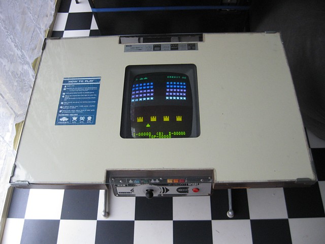
Here the machine is reassembled and working, the Black and White monitor now miraculously displaying in colour thanks to the original multi colour tinted plastic screen which fits between the CRT face and the surround. Unlike the Taito versions which used coloured plastic gels adhered directly to the face of the CRT this one is rigid and shaped to match the curve of the tube.
Double checking the power supply rails at the input to the game PCB after warming up all are still OK so the machine appears to be 100% functional. On that note I'm calling this repair finished and very happy with the result. And so, on to the next...
Web Resources (External Links) -
Space Fever (colour version) interconnection pinouts - CrazyKong.com
All images and text on this website are Copyright.
Contact: jbtech at telstra dot com