Nintendo Space Firebird PCB set
I have another Arcade PCB set on the bench for repair, this one is Space Firebird by Nintendo, released in 1980.
If Space Fever (1979) was Nintendo's answer to Taito's Space Invaders of 1978 then Space Firebird appears to be their response to Namco's Galaxian, released in 1979. An early full colour game with a starfield background layer and colourful alien characters which swoop around in swirling formations much like Namco's Galaga which was yet to be released, the following year.
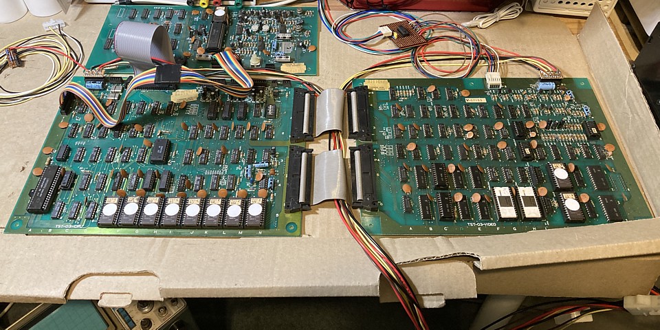
The PCBs themselves appear to be in great condition with no damage or obvious repairs but reportedly not running. The first step as with all pre-JAMMA games is to sort out a test lead to power the boards up and observe any output. In this instance the Space Fever test cabling which I prepared earlier will do nicely as far as the power supply is concerned but the colour video and control cabling is not interchangeable with Space Fever so these will need to be made up to suit.
To further complicate matters the RGB outputs from the Space Firebird PCB are inverted, compared to the more common positive Video required by most monitors. It would be possible to take the signal from an earlier stage on the PCB, prior to its inverting output stage but to avoid any need to modify or interfere with the original hardware I'll make up an external inverter for the RGB Video.
Interestingly, the set of circuit diagrams which I have for this game covers the Sega / Gremlin licensed upright version which uses an 'interface board' between the RGB output from the game PCB and the Wells Gardner monitor. The interface board looks like an afterthought to adapt the Nintendo PCB set to the U.S. made monitor and uses three gates of a TTL 74LS04 Hex inverter to reverse the R,G and B signals.
That's a surprising choice as a quick glance at the circuit diagram for Space Firebird confirms the RGB video is derived from an 8 bit digital to analog conversion and capable of 256 colour combinations. Putting the Red, Green and Blue analog outputs through three single bit inverters limits the range of colours available to 8, a reduction in image quality compared to the original Nintendo machines.
It intriques me that such an apparent oversight went into production by Gremlin, as documented. An analog inverting amplifier surely would not have been so much more difficult or expensive to implement. So for testing purposes I'll make up a simple interface board as per the Gremlin example but once the game is up and running will do a comparison between that and a fully analog signal conversion.
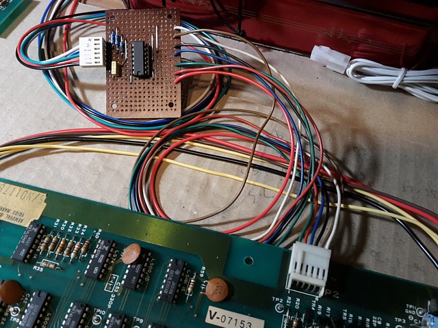
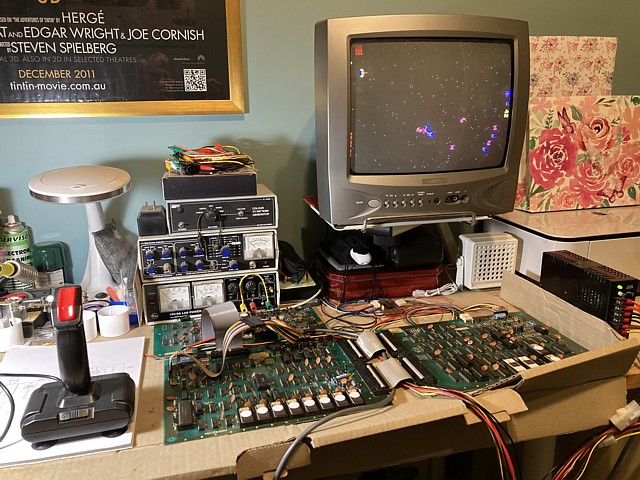
Setting up the Nintendo Space Firebird PCB set to test on the bench, I've made up a simple Interface Board for the inverted RGB video as per the Gremlin circuit diagram, increasing the value of its output resistors to 330 Ohms reduces the 5V output from the TTL inverter to a more reasonable 1V signal to suit my RGB modded NEC TV.
I've connected a standard arcade power supply to the PCBs using my existing Space Fever test lead but as yet have not made up a control cable to suit the Space Firebird pinout, that won't be needed until the game is running and inputs need testing. Meanwhile it's time to power up the PCBs and see if there is any video output.
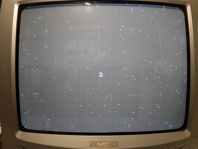
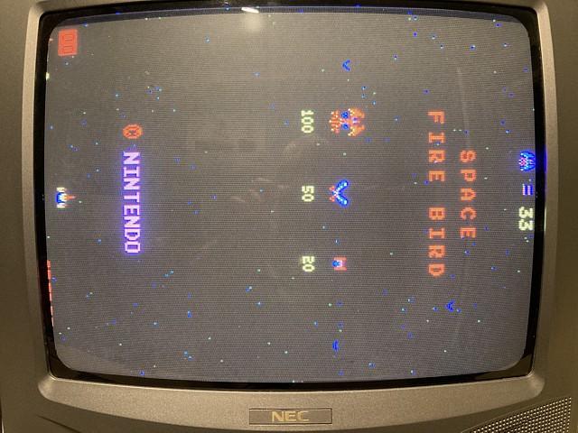
Any video from the PCBs is a good start and here there is a stable image with starfield background and what appears to be part of a sprite character in the centre of screen but no movement or sign of activity. At least the master clock signal and sync generation appears to be working correctly.
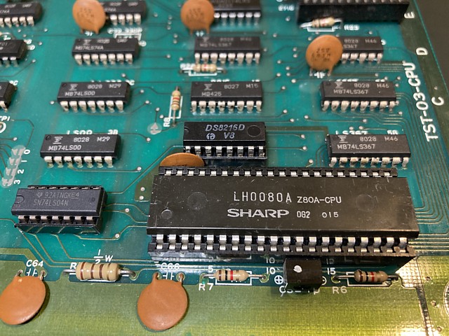
A good place to start checking the circuit is to look at the signals around the Z80 CPU, or in this case its Sharp LH0080A equivalent. To begin with, +5Volt, ground, clock and reset signals all look correct. Address and data pins are all active with correct levels so the CPU is doing something, at least.
Now looking at the control signals, /RD /WR and /MREQ are all active, suggesting the CPU is reading from ROM and presumably, writing to RAM. The /IORQ output from pin 20 is noticeably idle however so the CPU does not appear to be accessing I/O ports such as control inputs, DIP switches etc.
That could be a fault in the CPU, a short across that particular control signal or perhaps the program is not advancing to the point where this would normally occur, stuck in some sort of loop instead of running correctly.
Removing the CPU from its socket and substituting a spare, the symptoms are unchanged. From the CPU the /IORQ signal connects to a 74LS04 inverter in position 3A so to check if that IC is loading the signal I desolder it from the PCB, adding a socket. No change but as the original was a Fujitsu IC I install a new 74LS04 anyway.
That seems to confirm that the program is not advancing but stuck in some sort of loop so the next step is to verify the EPROMs to make sure the program contents are intact. The EPROMs on the CPU and Video PCBs are Fujitsu MB8516, 2kByte ICs compatible with 2716 EPROMs so my EPROM programmer can read these (and program replacements if required.)
The single EPROM on the programmable sound PCB is a 2708, 1KByte EPROM however which would require an adaptor to read so for the moment I will leave it in situ. After reading all of the other EPROMS I've confirmed their checksums match known Space Firebird ROM files.
So, the program EPROMs are OK but the program isn't running properly, why not? It could be a problem with the RAM but before leaping to that area let's see if the program is being read correctly by the CPU. After reset, the first thing the CPU will do is to read its first instruction code, usually from ROM and in the case of the Z80, beginning at address 0000.
To check if this is occurring we can look at the address inputs of the EPROMs in case an address buffer may not be working, their select lines to ensure the address decoding is functioning and their data outputs to see if the data being read from the EPROMs is reaching the CPU via any data buffers.
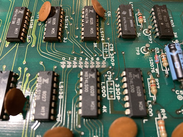
First checking the +5Volt and ground at the EPROMs, which is fine then the addresses, select lines and data there's an obvious issue here. Data bits 0 to 3 look 'normal' but data bits 4 to 7 are all stuck low. Having already verified the EPROMs we know they contain data and are capable of outputting, they are being addressed and selected but those four bits are always low. There must be something shorting these signals on the data bus.
That's a pretty obvious problem and admittedly I could have reached this point by simply probing all of the pins of the major ICs and looking for stuck signals. No matter, I prefer to trace problems from a logical starting point rather than taking a 'blanket' approach. Either way, we've only identified a problem and still need to find the solution.
Tracing a short across a data bus can be a bit of a challenge. In this case it's not a passive short and doesn't measure as a low resistance when the board is powered off. Once powered up, one of the devices connected to the data bus is continuously holding 4 of the 8 data bits low. To confine the issue to the CPU PCB we can disconnect the other two PCBs and confirm the fault remains as before.
An ideal tool for tracing this type of problem would be a 'current probe' which can detect a current flowing through a PCB track and help identify which device is loading the circuit. I don't have one unfortunately, these were never commonly used and now quite rare as they would not work with modern multilayer PCBs with high track and component density. Even second hand examples tend to be expensive and often not working as the probe tip which detects the current is very fine and easily broken.
When these arcade machines were being operated commercially any downtime was expensive so a quick repair was a higher priority than a neat one. A common approach to locating a short was to cut the PCB tracks at various locations until the short was isolated then join them together again by soldering wire jumpers across the cuts. Now these PCBs are more like Museum pieces than Money spinners a quick and dirty repair is no longer preferable.
On the Space Firebird PCB, Nintendo have actually provided a point where the data bus tracks can be cut and easily re-joined to isolate all of the peripheral components just leaving critical CPU related devices such as ROM and RAM in circuit. That's very thoughtful, designing a circuit to be repairable unlike most modern 'throwaway' technology. In this case though I don't want to disfigure the PCB in any way so will use a different approach.
To identify the faulty component I'll carefully desolder ICs which are connected to the data bus, one at a time beginning with the most likely cause, retesting each time and installing a new socket in each case. Adding a socket will assist with any future troubleshooting and minimise wear and tear on the PCB long term, keeping desoldering and resoldering of components to a minimum.
So, beginning with the Fujitsu MB425 (Intel 8216 equivalent) bi-directional bus driver in position 4B, this is a 4 bit device and only connects to bits 4 - 7 of the data bus. Fortunately I have some spare 8216 ICs and replacing the component appears to make some improvement to the fault symptoms. It hasn't corrected the problem but now there is some low level activity which was not apparent previously.
I suspect this component may have been the original point of failure but may have caused further faults as other devices connected to the data bus continued to run into a short circuit load.
The next most likely components would be two of the four 2114 Static RAM ICs, each being a 1k x 4 bit device so I'll try removing the ones in position 4G and 4H which connect to bits 4 - 7. Having done that the fault symptoms are unchanged so those components are most likely OK.
Powering the board on again to retest I noticed the P8212 Parallel interface IC in position 3G was hot to touch. This IC's inputs are connected to the CPU data bus and its outputs connect to the sound PCB via connector P1. After desoldering the IC and installing a socket the original issue is unchanged so the cause of this IC running hot is as yet unknown. I'll come back to this once I've solved the short circuit data bus issue.
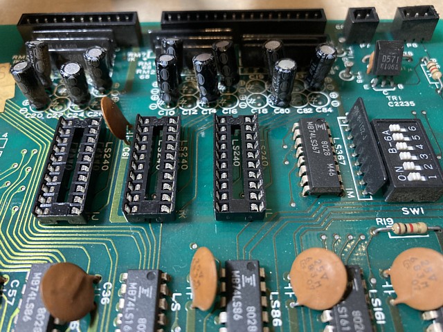
I'm running out of likely causes of the shorted data bus, my next suspects are 3 x 74LS240 inverting buffers in positions 1J, 1K and 1L which read the control inputs. I'd already checked their select signals to make sure the issue is not a bus conflict, where two or more devices are selected to output onto the data bus at the same time. That is not the case here so we're looking for a faulty IC.
Desoldering each in turn and testing, the last one in position 1L proved to be the culprit. Having removed it there is now activity and correct Voltage levels on all eight bits of the data bus.
That's solved the short circuit but I still need to replace the faulty component and I don't have any 74LS240 ICs on hand so I'll order a few (as they're still available) and replace all three for good measure. I'm also ordering a few 2114 RAM and P8212 parallel interface ICs in case these are also required, being obsolete the only available items would be either New Old Stock or 'pullouts' recovered from old PCBs so it might be handy to obtain some spares before the supply dries up completely.
I've been waiting on some ICs for the Nintendo Space Firebird PCB set, having traced a short circuit on the CPU data bus. My parts order has now arrived so it's time to install them and see if the fault is cured or if there are other issues.
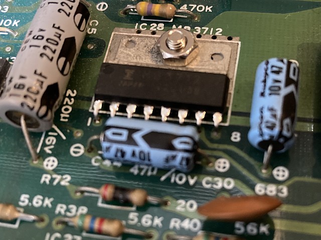
That gets the game running in attract mode with graphics looking correct, terrific! I haven't connected any controls as yet to test the game play and there's no sound - I've noticed the MB3712 audio output amplifier IC is missing from the ESS sound PCB so that will require some attention before we'll be able to hear any game sounds.
Space Firebird uses slightly different control wiring connections to Nintendos previous Space Fever game so my existing test lead for the game controls is not compatible. Instead I'm making up a new cable from the SIL header plug on the CPU PCB to a DB9 connector to use with my standard Quickshot 2 button joystick. The joystick was intended for older consoles or computers such as Atari 2600 or Commodore 64 but I've also found it convenient for bench testing arcade PCBs.
There's a header on the CPU PCB for each set of player controls, the Player one header having extra pins for the game start buttons. I'm making my control test cable with a 10 pin socket which will fit either header and I'll just use a wire link to add credits and select game start. Having done that the controls for both players are all working and the game plays correctly, flip screen operation also working as expected.
Time to test the sound hardware - once again, the connections for the sound from the Space Firebird PCB differ slightly from the previous Space Fever game. Space Fever's sound PCB had a low level audio output which was then amplified within the audio section of the video monitor chassis to drive the speaker. The Space Firebird sound PCB was fitted with an on board amplifier IC and capable of driving the speaker directly.
I understand the Nintendo cocktail machine which this game will be installed into still passes the audio through the amplifier within the monitor so the amplifier IC on the ESS sound PCB isn't really needed. It does appear to have been originally fitted to this board though so I'll order a replacement. Meanwhile for testing purposes I'll connect the low level audio from the volume Pot. on the sound PCB to the audio input on my AV modded NEC TV.
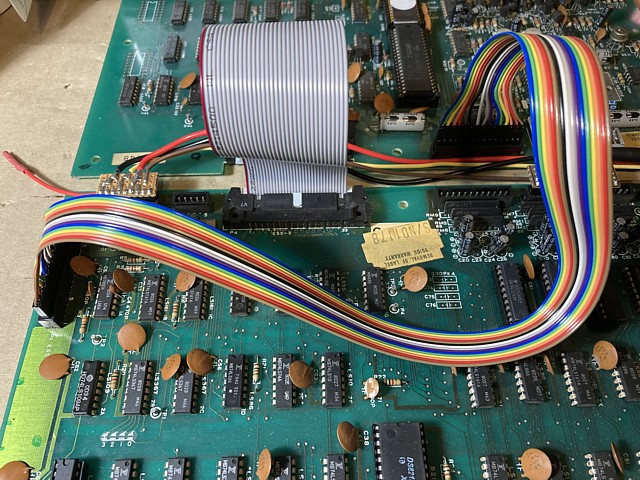
At first there seems to be a sound problem as the sound which is normally heard as the aliens fly around is playing constantly, even during attract mode. Shifting a cable to have a better look that problem seems to go away, it appears to be an issue with the control cable from the CPU to ESS sound PCB rather than the sound hardware itself.
That cable is a 15 pin rainbow coloured ribbon cable but not an original item. This one has individual sockets for each header pin as commonly seen on modern PC motherboard headers etc. but the pins on the Nintendo PCB may be slightly different and when tested with a multimeter some of the sockets must be making poor contact, measuring a high resistance.
The best solution is to make up a new cable using the nearest connector I can find to the original type, a 15 pin Molex housing with crimp pins and the correct 2.54mm pitch. I'll have to order those connectors so in the short term, extracting any socket pins from the existing cable which appear to be making poor contact and squeezing them slightly seems to help, the game and sounds now all working correctly.
The Space Firebird PCB set is running now, having sorted a problem on the CPU data bus. All game controls are working, graphics looking correct and all sounds present within the ESS sound PCB though not yet reaching the audio output. I'm waiting on a replacement for the audio amplifier IC to correct that issue.
I'm also ordering some connectors to make up a new interconnect cable between the CPU and ESS sound PCBs, the existing one having had some intermittent contacts but working for the moment.
Meanwhile out of curiosity I'm going to make up an analog video inverter to use between this PCB set and my video monitor, comparing the resulting image to that of the TTL inverter as used in the Gremlin version of the game.
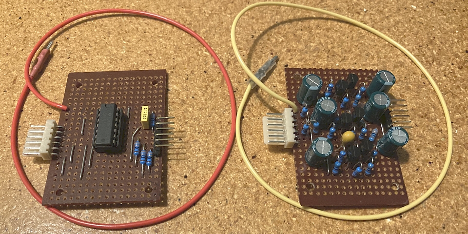
On the left, the TTL inverter which uses one gate of a 74LS04 for each colour Red, Green and Blue. As each colour output can only be On or Off the possible combinations are limited to the standard colourbar colours Red, Green, Blue, Cyan, Magenta, Yellow, White and of course Black.
On the right three channels of analog inverting amplifier which should faithfully reproduce the 256 possible colour combinations available from the Space Firebird's 8 bit Digital to Analog video conversion.
In both cases the sync is straight through, just placing a 330 Ohm resistor in series to reduce its amplitude to suit my RGB modded NEC TV monitor which only requires a 0.3V standard (negative polarity) sync signal.
 |
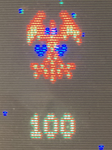 |
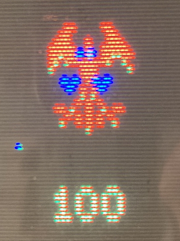
Now doing a back to back comparison between the TTL (left) and analog (right) video inverters I have to admit the difference is not as striking as I would have imagined. There are a few details which are missing from the TTL conversion but as Nintendo mainly used bold colours for the objects and text in Space Firebird the majority come through the TTL conversion unscathed.
Looking at the Space Firebird sprite above, there are a few pixels which are missing from the left image as well as some of the star field dots but the outlines and majority of details are not affected. It certainly does not impede gameplay.
So I'm beginning to understand why the Gremlin machine used the simplest, least expensive add-on to interface the Nintendo PCBs to their Wells Gardner monitors. Unless the Nintendo and Gremlin machines could be seen together, operating side by side it is unlikely anyone would notice the slight difference in the image quality.
Taking the opportunity to play the game, albeit with a vintage joystick and using a sideways display I'd call Space Firebird a bit of a hidden gem. The gameplay is on par with Galaga which wasn't even released until the following year and has a couple of unique features with the bomb which can be shot but then having to avoid its shrapnel and the Warp / shield function on button 2 which can only be deployed once for each ship.
To me this game is a perfect example of the upward trajectory that Nintendo were already on by 1980. Following Space Fever the previous year, a slightly enhanced Space Invader clone then leapfrogging their competition with Space Firebird, an early full colour game following in the footsteps of Namco's Galaxian but already anticipating gameplay elements yet to be seen in their sequel Galaga and well on their way to changing the game entirely with the release of Donkey Kong only a year away.
I've been waiting on a few parts to complete repairs to the Nintendo Space Firebird PCB set. The MB3712 amplifier ICs must be on a slow boat somewhere, meanwhile an order I placed locally has arrived including parts to make up the new control cable for the ESS sound PCB along with some capacitors for the power supply regulator module so I'll proceed with those.
Here's the new cable with 15 way Molex socket housings and crimp terminals at both ends. The socket pins are individually crimped onto the wires which have been separated near the ends of the cable and lengths trimmed to allow for the wires spreading out to suit the 2.54mm connector pitch. The ribbon cable I'm using is 16 way so the extra wire can just be peeled off and discarded however in this case I have used 2 wires for pin 15 which is ground.
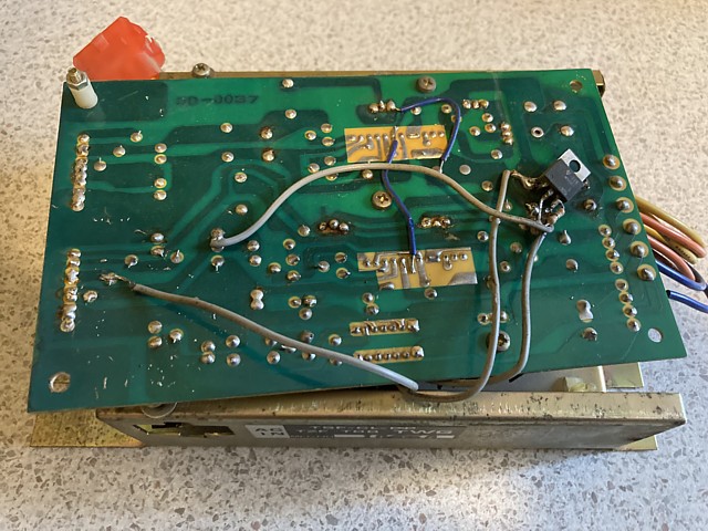
That done and re checking the game functions and all sounds working correctly I'll move on to testing and a bit of preventative maintenance of the machine's linear power supply regulator module. The power supply was reportedly working but I'll test it on the bench just to confirm and replace the electrolytic capacitors (most of which look old and original) for good measure.
The regulator module looks slightly different to the one used in Space Fever but that model was known for failing due to swollen and leaky capacitors so I suspect this one may be prone to similar issues. Having made up a list to order replacements I've selected parts with slightly higher Voltage and Temperature ratings and the correct lead spacing to ensure a neat fit on the PCB.
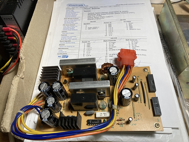
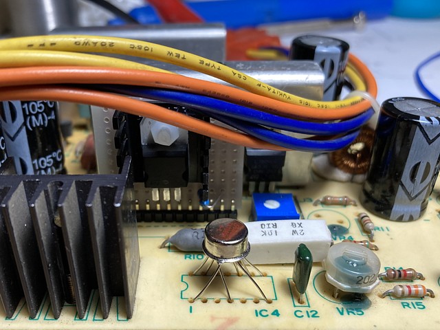
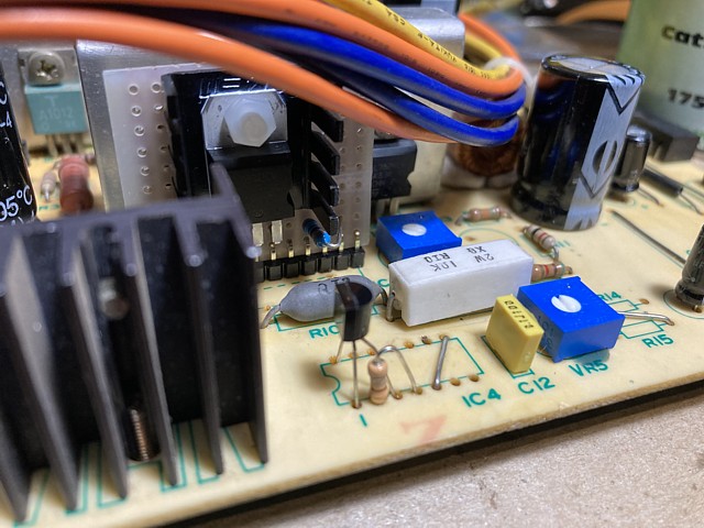
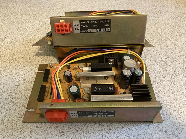
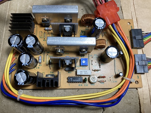
Here's the regulator PCB with new capacitors fitted and ready to test. I've looked at two original PCBs and C11 appears to have been omitted or deliberately removed from both so I'm assuming this is correct, will leave that space empty and test it as is. I don't have the transformer module here to power the regulator PCB but can feed an equivalent DC Voltage through the on board rectifiers in order to test the Voltage regulator stages individually.
Each of the three main regulator stages is preceded by a bridge rectifier and filter capacitor(s), powered by separate windings on the transformer. The +5V rail obviously has the highest current demand and uses a larger rectifier bridge and a pair of 3300uF capacitors for smoothing.
There's also a +24V output from the regulator PCB which drives the machine's coin counter, this is derived from the unregulated Voltage prior to the +12V regulator and controlled by a 7824 regulator IC. The unregulated Voltage from that rectifier must be at least 24 Volts to provide for that output.
Prior to testing each regulator I'll check the bridge rectifiers using my multimeter diode test. Although not expecting any problems it turns out one of the diodes in the larger bridge for the +5V supply is open circuit. Lucky I checked - when reinstalled into the machine and connected to the AC secondary Voltage from the transformer only one half of the AC waveform would be rectified, resulting in increased, 50Hz ripple going into the regulator circuit.
In fact, this may even solve a mystery. When I made up a list of capacitors on the PCB I noticed C1 and C2 which follow the rectifier for the +5V supply appear to have been changed at some point and their values were higher than those on the 'spare' regulator PCB, 3300 microFarad each instead of only 470 microFarad.
It could be someone noticed a high ripple Voltage which may have affected the +5V rail and increased their value, not realising the bridge rectifier was only half working. Even so, I don't think the higher capacitance would cause any problems so will leave the values as found. Meanwhile the bridge rectifier from the second regulator PCB tested fine so I'll borrow that one to replace the faulty component.
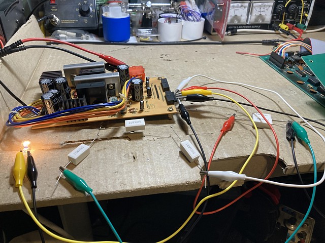
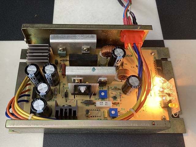
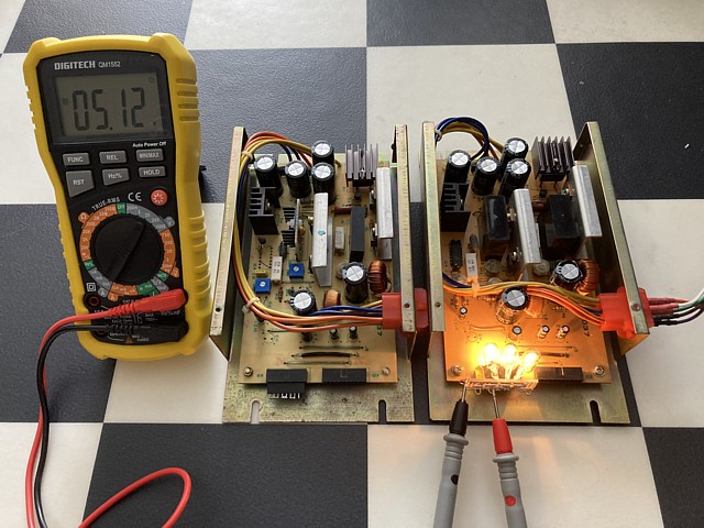
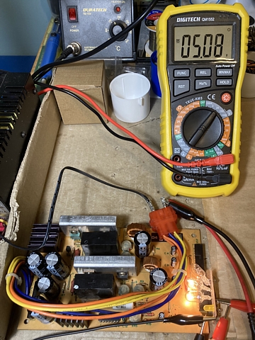
Testing the power supply regulators. In this photo my bench power supply is powering the +5V regulator via its bridge rectifier, supplying around 10VDC to its input while the +5V output drives a pair of 5W resistors in parallel, delivering a bit over 1 Amp according to the current meter (top right of photo). The Voltage measured at the output of the regulator PCB was steady at 5.07V.
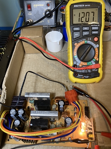
Repeating the test with the -5V supply the output Voltage was steady at around -5.04V, using a higher resistance load to reduce the current draw to less than 0.5A. Finally checking the +12V supply, initially there was no output so I guessed that regulator is linked to the +5V supply - it will not be on unless the +5V is also present.
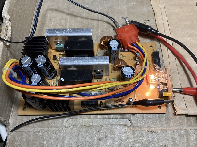
In order to test that rail I used a second power supply so the +5 and +12V regulators could be run together. The 12V bulb used as a load can be seen in the lower left of photo, switching on when the +5V supply was present. I also checked the +24V output (used to drive a coin meter) was present on pin 9 of the 9 pin power connector.
I'd nearly completed repairs to the Nintendo Space Firebird PCB set, just waiting on a MB3712 Audio amplifier IC to finish it off. As mentioned previously this part like many others on these older PCBs is obsolete so the only available replacements would be New Old Stock (NOS - if very fortunate to find any) or more likely 'pullouts' recovered from old PCBs.
A minor setback then when I received the two ICs from order (I usually order a spare or two, just in case) both looked pretty shabby, were obviously second hand and when tested neither worked. The first apparently had an internal short circuit and caused the 20 Ohm resistor which is in series with the +12V supply rail to overheat.
The second just appeared dead with no output whatsoever so the only practical option was to order another couple of ICs from a different supplier and hope for a better outcome. Meanwhile the 20 Ohm resistor which was still working but now looking pretty charred also warranted replacement so I ordered some new ones from a local supplier as this item is readily available.
Following another long wait the additional parts arrived and this time the result was a success. With the sound now working correctly and finally replacing that 20 Ohm resistor for good measure this repair is now complete. The Space Firebird PCB set is fully working.
But wait, there's more! I still haven't fully assessed that spare power supply regulator module or attempted to repair it so I'll look at that next.
The Nintendo Space Firebird PCB set is fully repaired now. I've also overhauled its linear power supply regulator module, replacing its electrolytic capacitors as well as the bridge rectifier for its +5V rail which revealed one open circuit diode when tested.
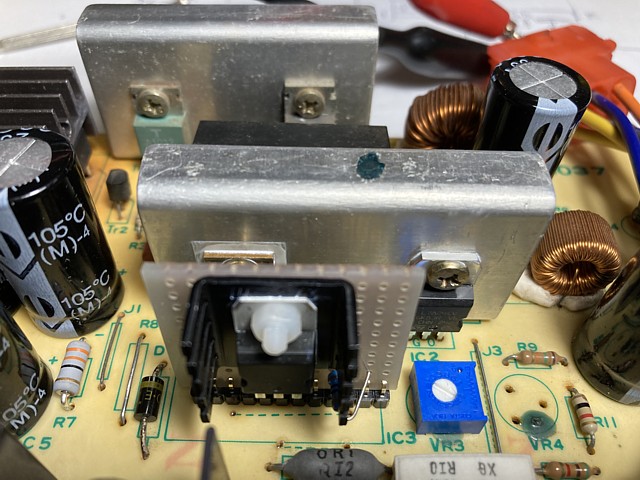
At the time I 'borrowed' the bridge rectifier from a second, spare regulator module but now I'll see if that module can also be repaired. This one was pretty dirty and obviously in poorer condition than the first but the most obvious difference was a major modification as can be seen in the photo below.
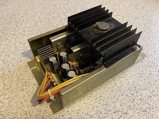
A large heatsink had been added with a TO-3 transistor or regulator (the part number is worn off) so at a glance it seems one of the module's original regulator circuits has been bypassed, most likely the +5V rail which has the highest current load.
Removing the board to trace the connections revealed this hideous modification which was perilously sandwiched between the underside of the PCB and the metal case, eeeeeek! The only option is to remove it all, return the module to its original configuration, test it and then repair as required.
So, the purpose of that modification was indeed to bypass the original +5V regulator which was presumably not working, using a 7805 3 terminal regulator IC with a series pass transistor. The theory was sound enough but the execution certainly left a lot to be desired.
The most surprising find was, after removing the modifications and returning the configuration to standard, the original +5V supply was tested and found to be working. I suspect the problem, if there was one at all was no more than a dry joint on the inductor L1 which I had spotted and reflowed as a matter of course when I tidied up the PCB prior to testing.
And with the +5V supply now working we can move on to testing the +12 / +24V supply rails. Unfortunately the +12V supply was found to be not working and the problem traced to a faulty hybrid IC module. This part would contain a regulator IC of some sort along with some additional components, all potted in resin.
I don't have the exact details for this module as the only circuit diagram I can find, for the Space Fever Colour power supply is similar but the module used is not identical and has a different pinout. In any case these modules would surely be unobtainable so I'll have to come up with an alternative which will do the same job and fit in neatly with the existing PCB and components.
Meanwhile I notice that the +24V supply which is only used for the coin counter, has had its 7824 regulator IC replaced with a 7812, reducing the output Voltage from 24 to 12 Volts. This appears to have been a rough and ready solution to the missing +12V rail, using the 24V output pin instead. That will definitely need to be returned to original configuration.
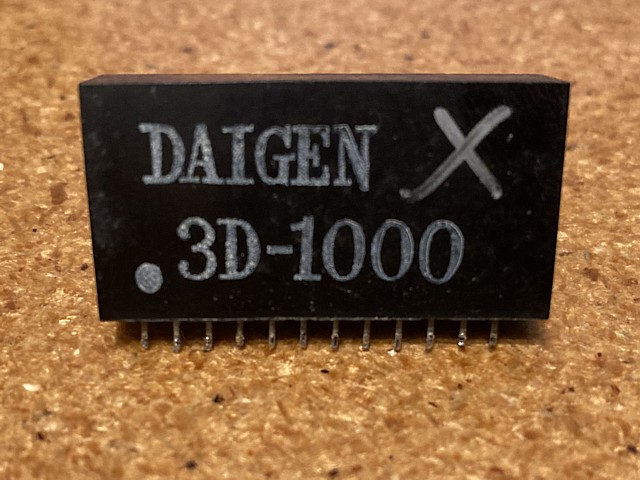
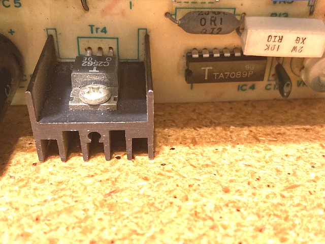
Just to see if there are any more surprises we'll move on to testing the -5V rail which on this PCB uses a Toshiba TA7089P regulator IC and a 2SC2562 output transistor. Disappointingly this is also not working, the transistor tests OK but the IC output collapses as soon as any load is applied.
Of course this IC is also obsolete and a search for replacements reveals very few available and most of those likely to be second hand parts removed from old boards. The metal can version, TA7089M does still appear to have some new old stock available at a reasonable cost so I'll substitute one of those.
I'm working on a spare power supply module, for the Nintendo Space Firebird PCB set which I've recently repaired. Unlike modern switchmode supplies it's a linear regulator module which has three sections, each powered by a separate secondary winding of the machine's power transformer.
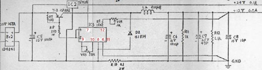
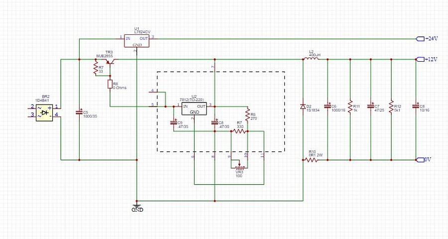
The +5V section is working now but the +12 / +24 and the -5V sections need work. I'm waiting on a new old stock regulator IC for the -5V so getting back to the +12 / +24V section, here is a circuit diagram for the equivalent part of the Space Fever Colour power supply.
The unit I'm working on at the moment, from Space Firebird seems to be the same apart from the hybrid module which has different pin connections so I've noted the connections for this version in red. Tracing the fault it appears the series pass transistor Tr3 is working but there is no control from the hybrid module IC3.
The hybrid module would contain a regulator IC and some additional circuitry encased in a resin block. The main reason for creating such a module is to make the overall circuit more compact and reduce the component count on the PCB which is fine as long as replacements for the hybrid module remain available.
This part having long since faded into obscurity, I can find no available spares or any technical details for it - the only option is to adapt the circuit to an alternative component. The rest of the circuit is fairly conventional, one distinctive feature being that the regulator draws current from the base of a PNP output transistor rather than supplying currrent to an NPN device.
The configuration is reminiscent of another linear power supply of the era, used in Taito's Space Invaders upright machines. A circuit of the +12V section of that supply is shown below:
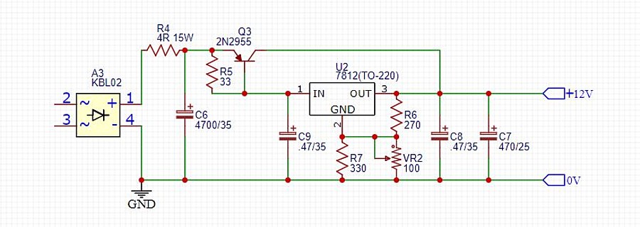
The two circuits above are fairly similar, Taito's design having the advantage of being a bit simpler and using a commonly available 7812 regulator IC to control its PNP series pass output transistor.
It should be straightforward to merge the two designs, substituting the 7812 regulator IC and surrounding components for the obsolete and unobtainable hybrid module from the Nintendo supply like so:
Continuing with repairs to the spare linear power supply regulator module for the Nintendo Space Firebird PCB set, I'm having to install some modifications to overcome the issue of unavailable original components.
I've made up a little module to replace the faulty hybrid regulator IC3 which comprises a 7812 regulator, a couple of resistors and tantalum capacitors (fitted to the other side of the board) as well as substituting new components for TR3, R7, R8 and VR3 on the main board as per the circuit diagram above. I've also returned IC2 to its original type, 7824 regulator IC.
Having followed a proven design 'borrowed' from Taito's original Space Invaders power supply module and testing to confirm the new configuration works as expected, it's time to move on to the -5V supply rail, parts having now arrived from order.
The -5V rail was not working when tested, its TA7089P regulator IC output collapsing as soon as any load was applied. The 2SC2562 series pass output transistor tested OK however. Searching for replacements for the obsolete Toshiba regulator IC showed very few, mostly shabby looking examples available presumably removed from old PCBs.
Surprisingly there did seem to be a few of the very early metal can versions, TA7089M still available which appeared to be new old stock. These would be compatible, in fact the circuit 'wafer' inside should be the same just installed into the very obsolete TO-99 metal can package. The only difference between the DIP and metal can versions being the pinout which after a bit of research I've confirmed as below.
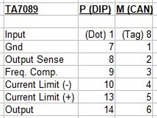
After ordering a couple and waiting for them to arrive I fitted one in place of the original component, carefully arranging the legs to fit the DIP outline on the PCB. Pin 7 is unused so rather than cutting the leg I've just soldered it into an unused position out of harms way.
It looks pretty retro but unfortunately the parts I received don't work. After double checking pin connections and testing both ICs in the Nintendo PCB as well as a simple test circuit there is no output from them at all. It could be both were faulty but there were no soldered or shortened legs so I suspect the components are not original Toshiba TA-7089M ICs and have most likely been re-marked with an incorrect part number.
Sourcing obsolete components is a very hit and miss affair with some genuine working parts carefully recovered from old PCBs and some damaged or faulty second hand parts being relabelled and passed off as new items as well as some outright fakes being sold as hard to find components at premium prices. In this case it seems the way forward is to cut our losses and adapt the circuit to a readily available, new and reliable component.
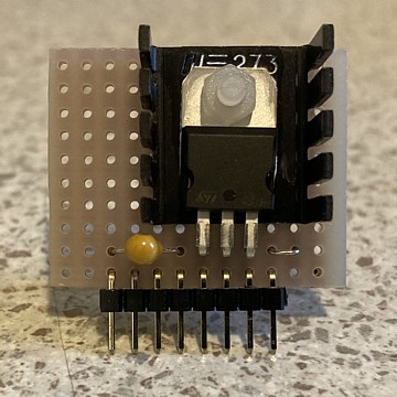
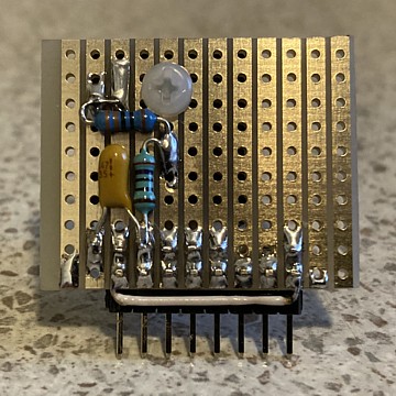
My simple solution which integrates with the existing PCB layout, a 78L05 regulator IC with basic Voltage adjustment and noise supression, having substituted new components for C12 and VR5 and utilising the existing output transistor TR4 (heatsink, left of photo). Tested and working well.
It's understandable that most surviving Nintendo machines of this era have simply had these rather unreliable and over complicated original modules replaced outright with modern switchmode supplies. If the original transformer is still present however the regulator modules can be repaired, utilising simpler and more readily available modern components if necessary.
With this power supply regulator module now fully working the Space Firebird PCB repairs have been successfully completed. So far though I've only tested the game PCBs using my own switchmode arcade power supply and the power supply regulators separately on the bench using resistors for a load, one Voltage rail at a time.
That's because I don't have the Nintendo machine's transformer module here to run the power supplies fully but it occurs to me that I do have a transformer assembly amongst my spares which should be similar enough to use for testing...
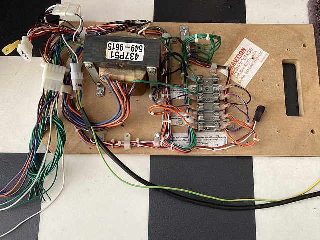
This spare transformer assembly is from an unknown machine, most likely a U.S. made upright cabinet from the '80s as it obviously was intended to work with a linear regulator module and not a switchmode supply. It has a single primary winding with 100V, 110V and 120V taps, no 240V however I can use it with a step down transformer.
The unit has four isolated secondary windings which are individually fused on the board, two which measure approximately 18VAC (with no load) and two of approximately 12VAC, once rectified these would be suitable to regulate down to +/- 12V and +/-5V rails.
The Nintendo supplies only have a single +12V rail as well as the two (plus and minus) 5V rails. There's also a +24V supply which is derived from the unregulated input Voltage for the +12V rail, passed to a 7824 regulator IC. If the peak Voltage from the transformer is less than about 26 Volts the +24V output may also be a bit low but this isn't critical as it is only intended to run the machine's coin counter anyway.
To get a quick indication if the supply rails are all present I've made up a little test socket which connects to the 9 pin header on the regulator module. It uses a 14V and two 6.3V light globes as loads / indicators for the +12V and +/-5V supplies and a yellow LED to indicate the presence of the +24V supply.
Testing each module in turn, all the Voltages are present and correct. To make measurement easier I've added test points for the four Voltages as well as ground.
And finally having confirmed both supply modules are working it's time to connect each one to the actual game PCBs, make some final Voltage adjustments and confirm the game is running correctly.
After several months (on and off) repairing, waiting for parts, re-ordering or finding alternatives when replacement parts turned out to be not working or completely unobtainable the repairs to the genuine Nintendo Space Firebird PCB set and two original linear power supply regulator modules are complete, tested and working.
Here we have two more Nintendo linear power supply regulator modules in need of repair. These ones are from other Nintendo Cocktail machines but very similar to the Space Firebird supply modules which I previously repaired. One reportedly has no +5 or +12V output, the other has a +5V output which is too high having been measured at 9 Volts instead of 5. Fortunately no game PCB was fitted to that machine at the time.
Testing on the bench confirms those symptoms so we'll begin with the module which has missing power supply rails. Having previously repaired similar units I know the +12V regulator will not operate unless the supply to the +5V section is also present so we could be looking at a single fault which affects both Voltage rails.
To begin with I'll test each diode within the three bridge rectifiers on the module just in case any are shorted or open circuit. Ive seen faults with the larger rectifiers for the +5V rail in previous repairs and once again this component is found to be faulty with three open circuit diodes resulting in no output at all.
Fortunately I still have a couple of new spares on hand so after replacing the bridge rectifier and re testing the +12V rail now appears to be working correctly.
That hasn't fixed the +5V supply however so it seems that problem is more widespread. Now checking the Voltages around the hybrid regulator module IC1 the supply Voltage to the regulator is present but there does not appear to be any current being drawn from the base of the PNP series pass transistor Tr1 via driver transistor Tr2. So it appears the hybrid regulator module is at fault.
The hybrid ICs used on these two units are not identical to the ones encountered in the previous repair - these ones have 8 pins and match the connections shown in the circuit diagram for the Space Fever Colour power PCB. The previous set had 12 pins each and a different pinout but must have been otherwise equivalent, the remainder of the circuit being unchanged.
In this instance the aim is to repair at least one of the two power supply units, retaining original type parts if possible so I'll swap the working hybrid IC from the 12V section of the other PCB into the 5V supply on this one. Having done that the +5V and +12V rails are both working as well as the +24V and -5V supplies which worked when initially tested.
All that remains to be done on this unit is some routine maintenance, replacing the original capacitors with new ones having improved Voltage and temperature ratings.
The first PCB is now working with a new bridge rectifier fitted, capacitors replaced and working hybrid module substituted for the faulty one. Both +5V and +12V supplies now present and correct.
 |
 |
Moving on to the second PCB which is now missing the hybrid module IC3 from the +12V regulator in addition to the over Voltage problem with the +5V rail. First checking the bridge rectifiers, this time rectifier Br1 for the +5V rail is found to have two open circuit diodes which would result in a half wave rectified output with increased 50Hz ripple and may have contributed to the failure of other components in the +5V regulator circuit.
Having replaced the bridge rectifier, now checking the Voltages around the hybrid regulator IC1 seems to confirm this component is causing the over Voltage condition of the +5V rail. So replacements will be required for both of the hybrid ICs on this PCB.
Those original hybrid modules are well and truly obsolete and replacements impossible to source so the best solution is to adapt a readily available 3 terminal regulator IC into each circuit to drive the series pass output transistors.
Beginning with the +12V regulator which was working prior to removing the hybrid module to repair the first PCB, I've made up a replacement module containing the 7812 regulator IC with Voltage adjustment by a 100 Ohm trimpot on the PCB in place of the original VR3.
 |
 |
The replacement module for the +5V regulator is similar, using a 7805 regulator and a 100 Ohm trimpot fitted in position VR1. I'm also replacing the original 2SA1012 series pass transistors with MJE2955 types and changing their emitter - base resistors to 33 Ohm as per the previous modifications detailed above.
The +5V circuit originally used an additional 2SA817 driver transistor which is no longer required, the 7805 regulator having ample current capacity to drive the series pass transistor directly. I've removed Tr2, R2 and replaced R3, R4 and VR2 with wire links.
With the substituted regulators tested and working as expected all that remains is to replace the original capacitors on this PCB, once again using new equivalents with improved Voltage and temperature ratings.
Both power supply regulator modules are now working, the first with original type components throughout and the second using modern substitutes where required to replace unobtainable original components.
Unfortunately, testing under load conditions reveals an underlying heat problem, especially in the area of the aluminium heatsinks for the +5V and +12V series pass transistors which are inadequate to dissipate the surplus energy released as heat by the transistors.
As with all linear power supply regulators, the difference between the input Voltage and output Voltage, multiplied by the current delivered is wasted power and released as heat by the series pass component. In the case of the +5V rail for example with a 10V AC input for a 5V DC output at a rated 3 Amps that would represent 30 Watts of input power for only 15 Watts delivered, the other 15 Watts being wasted as heat and an efficiency of only 50%
There's no doubt that these original Nintendo supply modules were a weak link in the machines and the number of revisions to the original design confirms the attempts which were made to resolve those issues at the time. Further modifications such as adding larger heatsinks or cooling fans may help but a better solution would be to use a more efficient power supply.
For original machines which now have a high value to collectors and only see occasional use it's worthwhile to retain the original type components where possible however if such machines were to be regularly operated today more efficient and therefore more reliable options are available in the form of switchmode power supply modules and wiring adapter kits.
So, on to the next project...
Web Resources (External Links) -
Classic 1980 Nintendo Space Firebird Arcade Game! - Youtube
Nintendo Space Firebird PCB repair final testing - Youtube
Power Supply Kit (TSF-CL, TST, TWG, SDM, TUB, TSC) - MikesArcade.com
All images and text on this website are Copyright.
Contact: jbtech at telstra dot com