Taito Space Invaders L shape PCB set
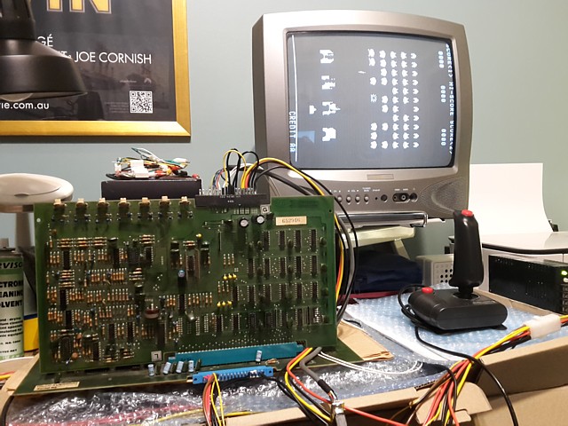
This is just a quick repair (well, quick by my standards anyway) of a Space Invaders L shape PCB set from an original blue Taito upright machine which was reportedly blowing fuses in the transformer / power block section. Expecting short circuit Tantalum capacitors as the cause, I also have the linear power regulator module from the machine to test and repair if required.
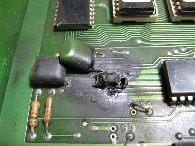
I'd already been alerted to one burnt out component on the main CPU board so the issue may be as simple as that however there could be subsequent damage, also with these older PCBs there are often multiple issues to begin with. After correcting this obvious problem a thorough test will be in order.
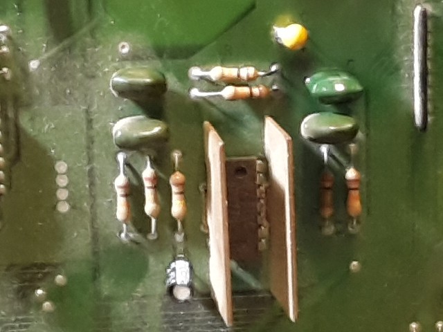
Surprisingly, all that black residue cleaned away revealing the undamaged PCB beneath. The component was a Tantalum capacitor placed across the +12V rail but its value was unreadable and not stated on the circuit diagram which I'm working from. Checking some high resolution images of similar PCBs found online the original component appeared to be 22uF, 16V.
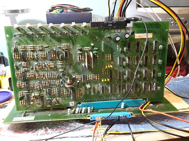
Replacing it with a new 22uF 25V Tantalum (these components now have a flameproof coating, thankfully) I turn my attention to completing a bench test lead to run the PCB using my standard arcade PSU and NEC TV, in this case the monochrome video from the PCB will be connected to the TVs standard composite video input.
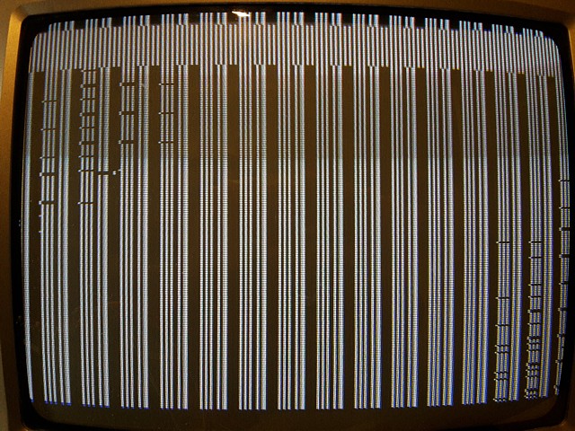
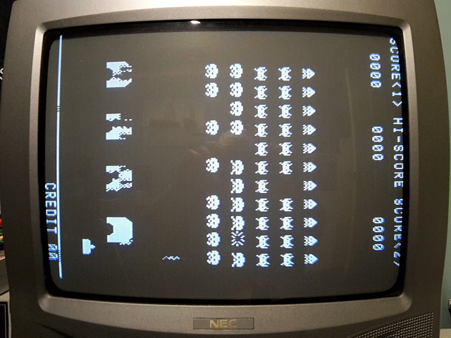
Powering it on, after a pause the on board watchdog timer resets the CPU, the attract screen appears albeit with some graphics issues but before I can look closer there is another flareup and puff of smoke, this time from the I/O Sound PCB.
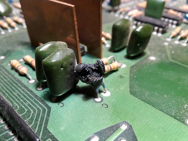
Quickly turning it off to have a closer look it's another Tantalum capacitor, this time 10uF 25V across the +18V rail. These components are known to fail with age but there is also some possibility this PCB was affected by an over-voltage power supply. All the more reason to carefully check the power regulator module which was installed in the machine.
The 0.1uF greencap immediately behind the Tantalum looks like collateral damage, a bit blistered from the flareup so along with a new 10uF 35V Tantalum I'll replace that as well.
Having set up this Space Invaders board set on the test bench and after some initial pyrotechnics from a couple of shorted Tantalum capacitors it's time to power it on again and see what other issues may remain.
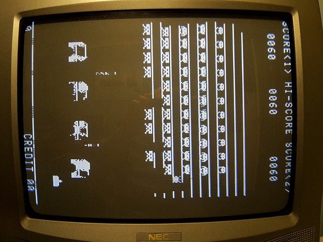
The attract mode does run and a game can be started which is good news. There's a bit of an issue with the invader and missile graphics but the text is displaying OK. The coin input, 1 player and 2 player start and fire inputs all work when tested, just using a wire link at this stage but there is no response to the laser base left and right control inputs for player 2.
Initially there's no sound at all, that turns out to be intermittent but even when sounds are heard some of the individual sound effects are missing or sound wrong. Another intermittent fault becomes apparent after the PCB has been running for a while and warms up the image disappears from the monitor, it seems the game continues to play without video when this occurs.
So that's at least four separate issues to address so far, in addition to the initial problem of shorted capacitors. Perhaps that 'quick repair' was a bit of wishful thinking - no matter, we'll tackle one issue at a time.
I've been progressing with the Space Invaders L shape PCB repair, adding some control inputs to my test lead but reconnecting it and powering it on again there's a setback. Now the game won't run at all with random patterns appearing on screen after the initial CPU reset.
This sort of thing often seems to happen with a 'new' repair job, additional faults appearing soon after first power on. In this instance I'm pretty sure it isn't something I've done, e.g. shorting some signals while probing the PCB etc. it may just be a component which was previously stressed and has now failed.
In any case, the solution is to take a step back, re-test Voltages and signals around the major components and search for clues. First up, all the supply Voltages at the PCB edge connectors are still correct when tested with a multimeter. The watchdog timer reset function is obviously still operational also the main crystal oscillator and sync generation are definitely working.
Selecting the internal 'test mode' by turning DIP switch number 4 ON prior to power up makes no apparent difference so the program may not be running or able to read the DIP switch port. I haven't yet verified the PROMs and it could be one has failed or perhaps the logic around the CPU, ROM and RAM is the issue.
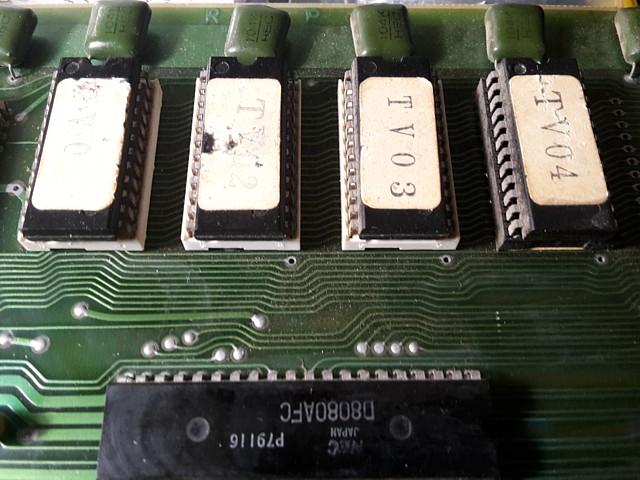
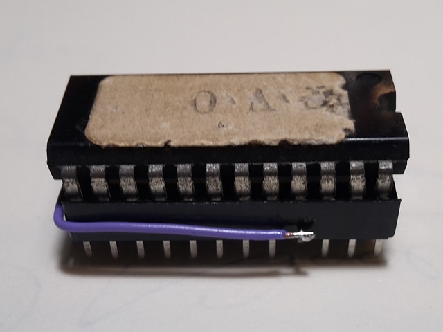
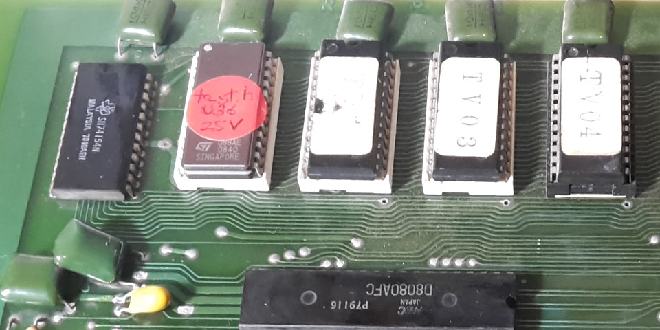
This PCB set is running the Space Invaders TV ROMset, on 16kbit (2k x 8) PROMs, probably 9316 type ICs. The majority of signals on these components are pin compatible with the 2716 EPROM (but not TMS2716) except for some of the select lines. To complicate matters, those can apparently be set differently during programming so not all 9316 PROMs use the same combination of logic levels on their select lines once programmed.
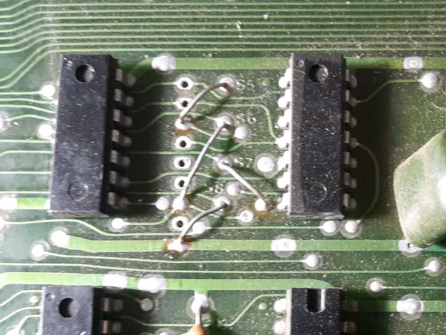
To confirm the combination used by this set of ICs I'm checking the selectable jumper links on the PCB, these are known to be correct as I have seen the game running with the current settings. So for these 9316 PROMs pin 21 is tied LOW using link S2, pin 18 is also tied LOW using link S4 and pin 20 is used as the chip enable, also active LOW which is the same as per the 2716 EPROM.
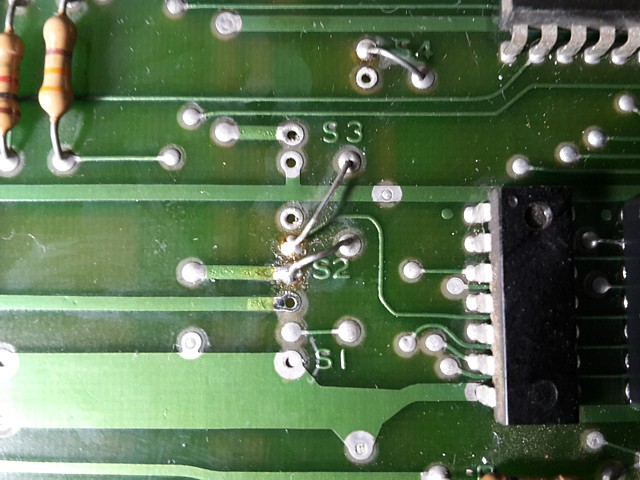
The address decoding can also be altered by moving PCB links, in the case of 9316 or most 2716 ICs there is no difference but these link settings are not suitable for 2708 or TMS2716 EPROMs which require three Voltage rails (+/-5 and +12V) and must be set accordingly. Conversely, link settings for those EPROMs are not suitable for the types in use here.
The only difference to the 'strapping' from the 9316 to the 2716 is pin 21 - which on the 2716 is VPP and recommended to be tied HIGH (+5V) during read operations. In practice however most variants of 2716 will be readable whether pin 21 is tied to 0V or +5V so in many cases the 2716 can be plugged in with the same link settings as pictured and will still work.
If not, link S2 could be changed from LOW to HIGH (moving it down to the next PCB pad in the photo) but this would prevent a mixed set of PROMS and EPROMS from being used as setting pin 21 HIGH would cause the 9316 PROMs to be de-selected.
It also means to read and verify the PROMs using my EPROM programmer I need to make up a little adaptor using a 24 pin IC socket, bending pin 21 away from the programmer's ZIF socket and soldering a wire to tie that pin to 0V from pin 12. Having done that the first PROM reads and verifies, its contents matching the checksum for TV01 from the SITV1 ROMset as listed in MAME.
So, enough research; back to the repair at hand. To narrow the search area I'm substituting a Space Invader Test EPROM in place of the TV01 PROM and temporarily changing the S2 link to HIGH which will also disable the other 3 PROMs.
Although the SITV ROMset includes virtually the same test program, the standalone Test ROM will boot directly into test mode without needing to read the DIP switches or access the higher ROM addresses. If that still doesn't work, at least there will be not quite so many possible causes.
It doesn't run, even in this simplified configuration so the next step is to probe the signals around the CPU and EPROM to identify the reason. Looking at the address lines from the CPU and then, as they arrive at the EPROM, Address line A6 appears wrong with a very long rise time, looking more like a sawtooth than a squuare waveform.
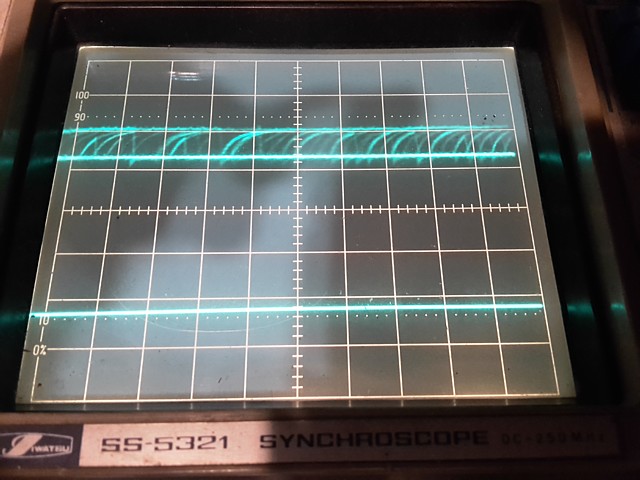
That one might have been hard to find with a logic probe as the levels were OK but the oscilloscope makes it pretty clear. That address line is buffered by a 74LS08 AND gate in location 3PR so replacing that, also installing a socket fixes the problem and we're back on track.
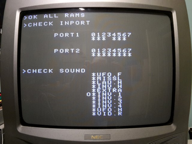
The Test ROM screen appears, cycling through the game sounds - some are initially present, some still sounding incorrect and after a short while all sounds become distorted and fade out altogether. At this point I switch it off and revert back to the original program ROM to confirm the attract mode runs and game starts as before, still with the graphics and player 2 control issues.
The interesting thing about the Player 2 controls is that although supported by the game program the 2nd player inputs are not implemented on the Taito L shape PCB set which was only ever fitted to upright cabinets with 1 player control panels. The single player inputs are simply connected to both ports 1 and 2 via a multiplexer so if the controls work for one player and not the other the multiplexer itself becomes the main suspect.
Even more interestingly, the Invader and missile graphics are moved on screen by a set of shift registers on the I/O sound PCB and the resultant image data is returned to the CPU board via the same set of multiplexers so a faulty one could be responsible for both the control and graphics faults.
The multiplexers are 74153s and I have some 74LS153s in stock which should work well so I'm replacing ICs 15 and 18 which handle the player 1/2 Left and Right inputs as well as 4 bits of the shifted graphics data, fitting new sockets as well. Having done that the graphics problem is solved as well as the Player 2 control inputs. That's two faults to cross off the list!
The Space Invaders L shape PCB set is up and running now, conrols and graphics working correctly so it's time to move on to the sound issues. First up, the intermittent problem where the sounds fade out and stop working altogether, usually after the game has been powered on for a few minutes.
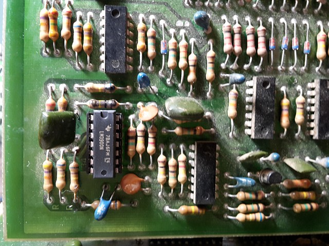
Checking the complementary outputs from the preamplifier stage at pins 4 and 10 of IC 23, an LM3900 quad op-amp the audio signals are still present though there is no sound from the speaker, confirming the problem is beyond that point in the final amplifier stage.
The power amplifier is an LM377N and runs from a +18V rail when installed in the machine but for testing purposes is connected to the +12V supply from my standard arcade Power Supply. Reluctant to write off the amplifier IC prematurely I try a few tests;
Firstly, cooling the IC with some freeze spray does not bring the output back, which seems to clear the IC of a thermal fault. Checking the outputs now, DC level of the two complementary outputs should sit at about 1/2 of the supply Voltage which would provide for maximum output power but both are only around 2V with no audio apparent on the outputs at all.
These operating conditions should be set up by a bias Voltage from pin 1 which is internally divided from the applied Vcc on pin 14. Checking the bias signal I notice the Voltage which is smoothed by a 100k Ohm series resistor and 10uF electrolytic capacitor to ground, is wrong and then spot the capacitor has been replaced, fairly recently and installed 'backwards'.
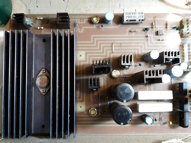
I didn't think to take a clear photo of it before removing but zooming in on a previous photo of the board you can see the capacitor to the lower left of the heatsink with the grey stripe and '-' symbol facing up, it's actually adjacent to the '+' symbol on the PCB which isn't clear in the photo.
That was one of about 10 capacitors which were replaced by persons unknown, at some point prior to it being purchasesd in a non working state. There's 4 Electrolytic capacitors including one in the preamp stage near the volume control, 2 at top right across the +5V and +12V rails and a bunch of 6 Tantalums.
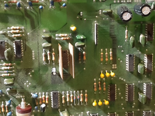
Fortunately the only capacitor which was reversed was the one on the bias circuit where the current available was insufficient to cause further damage. Replacing the capacitor with a new 10uF electrolytic, correctly polarised cures the intermittent sound problem.
Incidentally, in the photos above you can also see the 10uF Tantalum and 0.1uF greencap which I've replaced as per the earlier text, just above and to the right of the heatsink.
Now that the sounds are working overall it's time to check and repair any individual sounds which are missing or incorrect. So, returning to the inbuilt test program and listening to each sound in turn, firstly the UFO flying sound is working, fortunately as this sound is generated by the obsolete and fairly scarce SN76477N Complex Sound Generator IC.
Next, the Laser Base firing sound is incorrect, missing a noise component. It sounds like 'peep' where it should be something like 'pssssssht". The Laser Base Explosion sound is completely missing, both of these issues are most likely due to absence of the 'noise' signal which is generated by ICs 26 and 25.
The Invader hit sound, bonus Laser Base and the iconic 4 note Invader marching sounds are all present and correct. That only leaves the UFO hit sound which is also missing.
The UFO hit sound is generated by ICs 34 and 33, controlled by signal SX10 so starting there and tracing the signal to the first stage of IC34, another LM3900 there's no response on its output. Replacing that IC, installing a socket as well restores the sound. IC33 appears to be working OK and didn't need replacement.
So, on to the 'noise' generator which provides a white noise style hissing sound component used in shooting and explosion sound effects. It begins with a free running oscillator using a 4070 CMOS exclusive OR gate IC26 and passes that signal via a 4066 CMOS quad analog switch IC25, with various feedback loops to 'randomise' the pure tone signal.
Checking the first stage, there is no oscillation fronm the 4070 so it looks like that is faulty. I don't have one in stock nor the 4066 so I'll have to order a couple. At least they appear to be readily available.
I've been working on this Space Invaders board set from an original Taito upright machine and the game PCBs are working now apart from two of the sounds.
There was one other suspected problem, the video seemed to be dropping out after a while - this turned out to be a side issue caused by a poor contact on the bench test lead which I made specifically for this board set.
I had connected the game's monochrome composite video output to the TV monitor using a cable with standard RCA connector but the connector itself was a bit old and tarnished, the ground sleeve making poor contact with the TVs composite video input connector.
As a result the signal was not properly terminated by the TVs 75 Ohm input resistance so the video level was higher than a standard 1 Volt signal. Although initially seeming to display correctly the image would eventually blank, probably due to some internal overload protection in the TVs signal processing circuit.
So, having resolved that incidental problem in addition to the repairs above the game is running and playing reliably apart from the aforementioned sounds. I've now ordered a couple of ICs to continue with the sound repair so in the meantime I will begin testing the machine's linear power supply regulator PCB.
The original power supply fitted to this iconic '70s arcade machine is old school, using a multi tapped transformer with linear Voltage regulators on a separate PCB with several finned heatsinks to dissipate the surplus energy from each of the regulator ICs and series pass output transistors.
There are separate circuits for the +5V and +12V supplies also -12V which is not used directly for Space Invaders but is further regulated down to provide the -5V rail. There's also an unregulated +18V supply for the audio power amplifier and a Power On Reset timer which holds the CPU reset on briefly until power supplies have had time to stabilise.
The original fault symptom was fuses blowing in the Transformer module, that was most likely caused by the short circuit capacitors on the game PCBs - but what caused those? It's possible the power supply regulator may have a fault, outputting Voltages which were too high and damaging components on the game boards in the process.
In fact, the Tantalum capacitors going short and blowing a supply fuse could even have protected sensitive components such as processor and memory ICs from failure due to an excessive supply Voltage. In any case, the supply needs to be checked to ensure the problem does not recur.
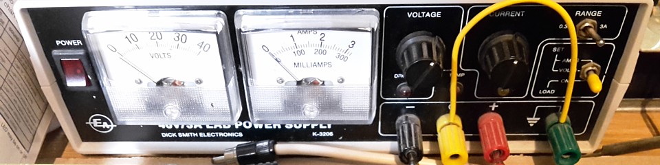
To test this module on the bench without a transformer module handy and without risking connection to the game PCB I'll be using my bench power supply as the input Voltage to each regulator in turn and connecting suitable resistors to the output rails to test them under load conditions.
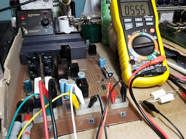
But first, I'm checking each of the 3 on-board bridge rectifiers using my multimeter diode test. Instead of applying the AC Voltage from the transformer here I'll be setting my bench power supply to the equivalent DC Voltage which will be sufficient to test the Voltage regulation stage. The input for the +5V regulator is DC anyway, the rectifiers and large filter capacitor being located in the transformer module.
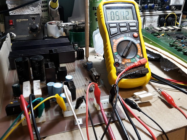
Beginning with the +5V rail the regulator works well, initially set for about +5.12VDC at the output terminals and the Voltage adjustment working correctly. That's a good starting point, allowing for some loss in the machine wiring without risk of the Voltage being too high at the inputs to the game PCB. Ideally it should be checked and adjusted as required when reinstalled.
Testing the +12V rail now the regulator fails its test. The 7812 regulator IC appears to be driving the series pass output transistor to saturation. It's not regulating at all, the output Voltage varies with any change of input Voltage or current draw. This looks like it could be the root cause of most of the other issues. I'll try replacing the 7812 and test it again.
Before I disconnect the test leads, I'll check the -12V supply which is a very similar circuit. Sure enough, it has a similar problem. That could have gone unnoticed for some time as the -12V doesn't connect directly to the game PCBs however the increased Voltage would increase the heat and risk of failure of the -5V regulator. Fortunately the -5V supply has survived and outputs a correct -5.10V when checked.
Quick checks of the unregulated +18V circuit and the Power On Reset timer which is powered by the +5V rail confirm these sections are working as expected. So I'll need to replace the two 7812 regulators used in the +12 and -12V supplies and retest.
Incidentally, the -12V circuit doesn't use a 7912 negative Voltage regulator as one might expect, the two supplies are basically positive Voltage regulators except the -12V supply has its 'positive' output connected to 0V. This configuration is only possible as each regulator is powered by a separate, isolated secondary winding on the transformer.
I'm working on the linear power supply regulator PCB from an original Taito Space Invaders upright machine, the game PCBs are up and running on the test bench but I'm waiting on a couple of parts to complete the repairs to the game sounds. Meanwhile, the power supply has problems with both the +12V and -12V rails which are over Voltage and not regulating correctly.
It seems the 7812 regulator ICs used in both are over driving the PNP output transistors so the most likely solution is to replace the ICs... But having done that the problem is not resolved. Although there is some control of each Voltage using the respective trimpots the range is from around 15 to over 16VDC for both.
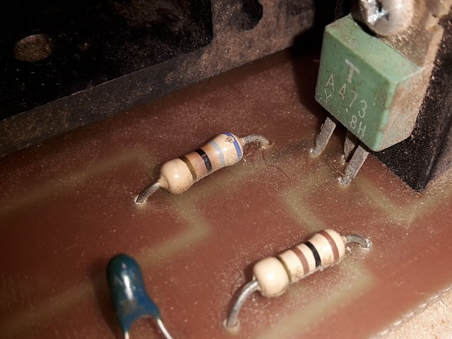
Checking other components around the output transistors, the 33 Ohm resistors which connect from Base to Emitter appear to be open circuit. This would account for the transistors being over driven and consequent increased output Voltage. On closer inspection it becomes obvious that these resistors and a number of others on the PCB have been recently replaced.
The original resistors would have been fairly large 1/2Watt carbon resistors and these have been replaced by more modern and physically smaller 0.5W metal film resistors. That in itself wouldn't be a problem but I now realise the replacement parts have the wrong value according to their colour coded stripes.
These particular components would have originally had the colours Orange, Orange, Black, (space), Gold - meaning 3 3 _ Ohm, 10% tolerance. The resistor colour code is widely published however it's not always mentioned that components with a 1% tolerance often have an additional band, meaning the multiplier is the fourth band on the resistor body and not the third.
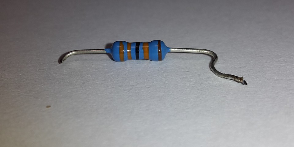
So the new resistors which have been fitted read Orange, Orange, Black, Orange, Brown meaning 3 3 0 000 Ohm, 1% tolerance - that's 330k Ohm, the resistors are not open circuit after all but their value is incorrect by a factor of 10,000! Checking the other non-original resistors on the PCB there are eight in total and every one is incorrect.
Most have the same issue with the multiplier band having been misread but there are also a couple where Red bands have been mistaken for Brown and Vice Versa. Admittedly, the coloured bands used on these blue bodied metal film components are far less distinct particularly Red, Orange and Yellow which all appear like shades of Brown. It's a mistake which is easily made.
The best advice I can offer regarding resistor markings is always double check your resistor value using your multimeter before fitting. It takes a couple of seconds and could save hours of wasted time and catastrophic damage to your precious machines.
So, all those resistors need to be replaced again using correct values. In the case of the 33 Ohm Base-Emitter (shunt) resistors I'm using an even higher spec. 2W metal film component to hopefully ensure these will never fail. It's not clear why so many resistors were previously replaced, the majority of which are not stressed in normal operation and would not routinely fail anyway.
There is one other resistor I've noticed which is an original part and still measures OK but is showing signs of overheating. It's a 68 Ohm, 1/2W so I'll replace that one, also upgrading it to a 2W metal film. With that done and repeating the test procedure all the supply rails are now working correctly.
It's still unclear whether there was a fault on the regulator PCB originally or not. There's obviously been some work done around the +18V supply including a new bridge rectifier but the problem on that rail may have actually been caused by the short circuit Tantalum capacitor on the I/O Sound PCB which I've since replaced. It's difficult to know which was the cause and which was the effect.
I'm on the home stretch with the Taito Space Invaders PCBs and power supply regulator. The 4070 CMOS ICs I've been waiting on have arrived so replacing IC26 on the I/O Sound PCB, adding an IC socket and retesting, all the sounds are now present and correct. The game PCBs are fully working and, having also repaired the power supply regulator PCB, all that remains is a bit of preventative maintenance .
It's impossible to guarantee the machine will not fail again at some point, the reality is these boards are well over 40 years old and the majority of components are still original. As the power supply is a common point of failure I can hopefully extend its working life by renewing the capacitors on the regulator PCB, being the components which are most prone to deterioration over time.
A couple of these may have been replaced fairly recently but without knowing exactly when (or why) the best option is to replace the entire set with new, high quality components. There are 20 capacitors in total, mostly Electrolytic and Tantalum. I'm sourcing replacements of equal value with the same lead spacing and slightly higher Voltage and temperature ratings where possible.
I'm just waiting on the last couple to arrive from order. Once installed it's a case of re-testing the board to ensure there are no new faults, bridged tracks etc. and the job will be done!
I've repaired the Taito Space Invaders L Shape PCB set and its power regulator module and as a matter of course have also renewed the capacitors on the power module. To this end the last couple of parts have arrived from order, I've fitted them and the job is finished.
The next step is to return them to the machine and after a few simple checks and adjustments hopefully have it working at last. I won't be doing that in person but will add a few details here to assist with checking and setting up the Voltages once fitted to the machine.
Before turning it on the first thing to check would be the wiring within the machine, making sure all the connections from the power module to the two edge connectors on the game PCBs look correct and are fitted correctly. The edge connectors may have a key inserted to ensure correct alignment but this is often missing or omitted so it helps to visually align the edge connector contacts with the PCB 'fingers' to ensure best connection and avoid shorts between adjacent contacts. Make sure the edge connectors are the right way around and not reversed and use a small mirror if required to align the contacts as the edge connectors are fitted.
So, assuming all the machine wiring looks good and given that the pre-adjustments have been made on the test bench it's time to turn the machine on briefly and look for activity or any sign of problems. If the machine doesn't seem to run, power off and double check fuses on the transformer module otherwise proceed to setting Voltages.
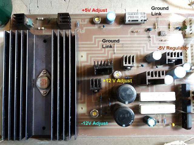
In this photo of the Power Regulator module I've added locations of the Voltage adjustments as well as indicating the -5V regulator and two convenient ground points. The Voltage measurements will be made at the input to the game PCBs to adjust for loss in the machine wiring except for the -12V rail which is not used directly on the Space Invaders PCB. The -12V supply is further regulated down to provide the -5V rail so the adjustment can be checked at the input to the -5V regulator.
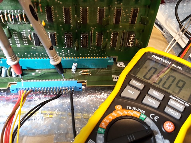
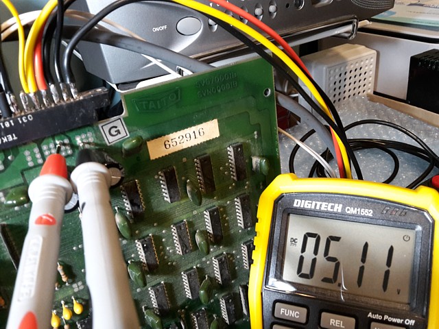
The first and most important Voltage rail to check and set is the +5V, measured here as it enters the main PCB, after the edge connector contact. Adjust for 5.0 to 5.1V DC. If problems setting this Voltage there may be issues with the diodes or large capacitor on the Transformer module.
If necessary to check the unregulated (input) Voltage for the +5V supply, the Voltage across the two terminals on the large capacitor within the transformer module can be measured. Measuring DC Voltage across the capacitor I would estimate a reading of around 13V being the 'peak' DC level from the rectified 9-0-9V windings. Changing the meter to read AC Voltage now, the AC (ripple) Voltage should be quite low - if more than 1Volt the capacitor probably needs replacement and the two diodes should also be tested.
If the +5V setting is OK and the game is working, move on to set the +12V rail.
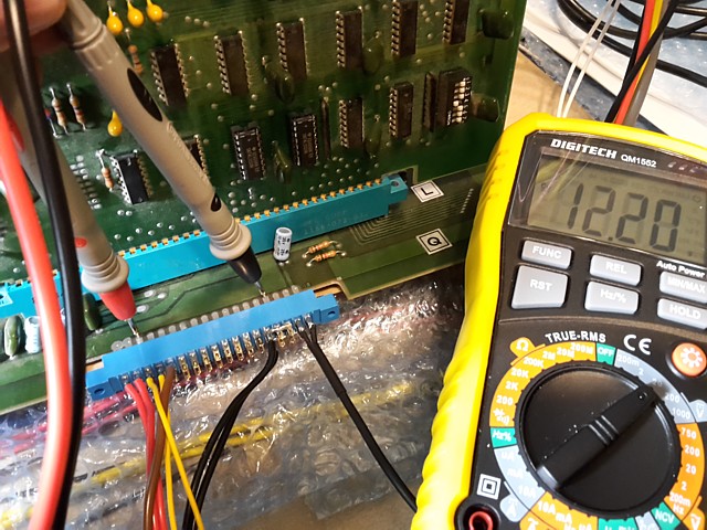
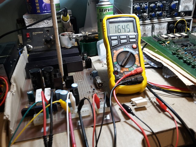
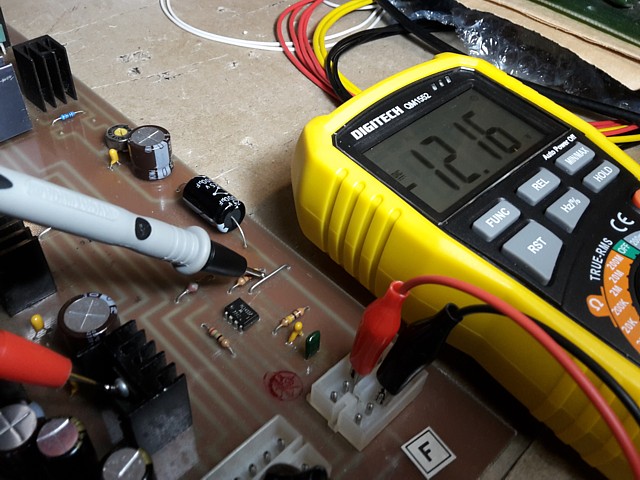
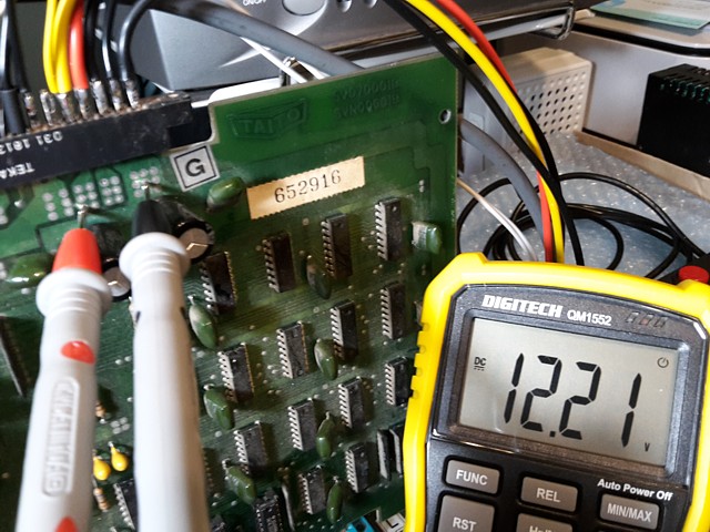
Checking the +12V rail as it enters the main PCB. Once again, aim for 12.0 to 12.1VDC (the Voltage in this photo is a little high but still OK as my bench test setup is using a standard arcade PSU which does not have a separate adjustment for the +12V rail).
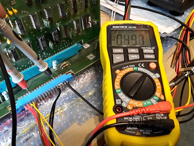
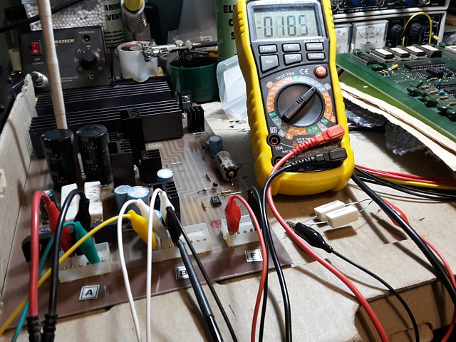
The -5V supply is not adjustable in this case but should be checked as it enters the main PCB. -5V plus or minus 0.1V is ideal.
The +5V and +12 supplies can also be checked where they enter the I/O Sound PCB. If there is much variation between these readings and the readings on the main PCB suspect the machine wiring or connector contacts.
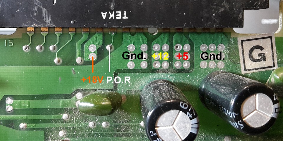
A couple of final checks on the I/O sound PCB, measure the Voltage at pin 10 component side - should be around +18V, if not present check fuses on the transformer module. Also, check the Voltage on pin 9 - should be zero or nearly 0Volts. That pin is the Power-On-reset signal and should be Low once the power supply is working, to allow the game PCB to run.
That's it! if all those Voltages are present and correct the board should work as reliably as possible. Hopefully the monitor and controls are functional and the machine will be ready to go, enjoy.
Web Resources (External Links) -
Taito Space Invaders Upright ('L' Shaped) Board Pinouts
All images and text on this website are Copyright.
Contact: jbtech at telstra dot com