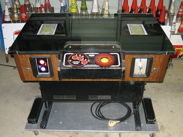
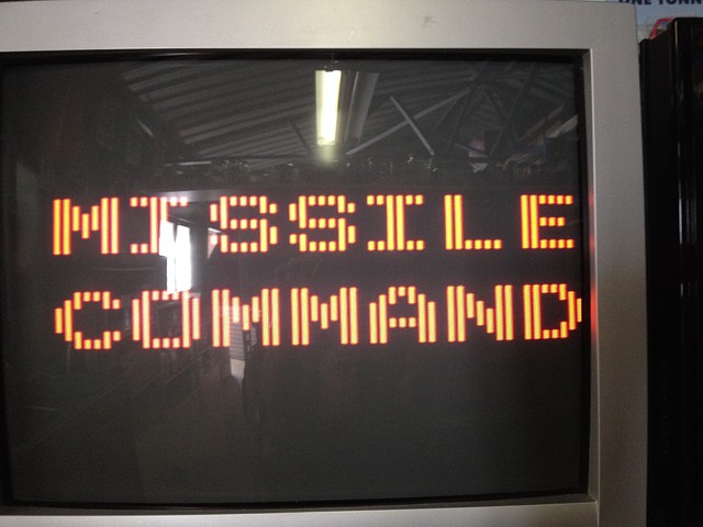
Taito Missile Command TT
During the 'Golden Age of Videogames' demand for new machines was so strong that competing manufacturers sometimes worked together, producing each other's games under licence. This is the product of one such alliance.
Atari manufactured its 'Missile Command' in the USA in Upright, Cockpit, Cabaret and Cocktail variants. Apparently, for the UK Sega produced an upright and a cocktail version using Atari's game PCBs while in Japan, Taito produced this cocktail version for the Japan and Australia markets, referring to it as a TT (TableTop) machine.
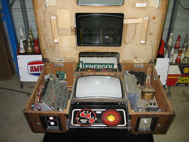
This one is complete and original internally but had issues with both the Atari manufactured game PCB and the Toei 14" Colour Monitor
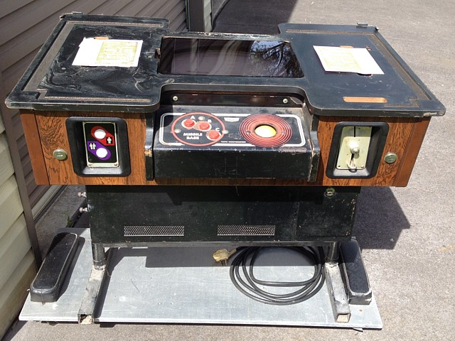
On the outside, the original glass was broken and has been replaced and, like many of the Taito cocktail units, the legs had weakened and these have been repaired with new square tube.
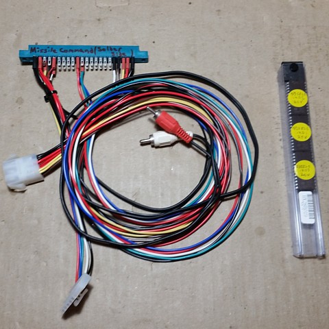
The only way to work on the game board is out of the machine so I made up a simple test cable. Initially it just has power, video and audio connections. An off-the-shelf arcade type power supply is being used for testing which must have -5V as well as +5V and +12V. As the +5V is adjustable, we start by setting it to about 5.1V with no load then readjust once the PCB is connected.
When approaching a repair the hope is always that a single fault will be detected which, once corrected, restores the unit to perfect working order. If the machine has a known history and just recently stopped working that may be the case but without any clues to the machines past or when it last 'worked' that is a bit unlikely...
When Powered up, this board presented us with a 'flashing screen', usually white but occasionally blue and accompanied by 'tearing' or loss of sync - more of that later. There is a diagnostic mode available by grounding a 'Test' pin which begins with a RAM test, outputting a sequence of beeps as there is no hope of video at this stage if a RAM chip is faulty.
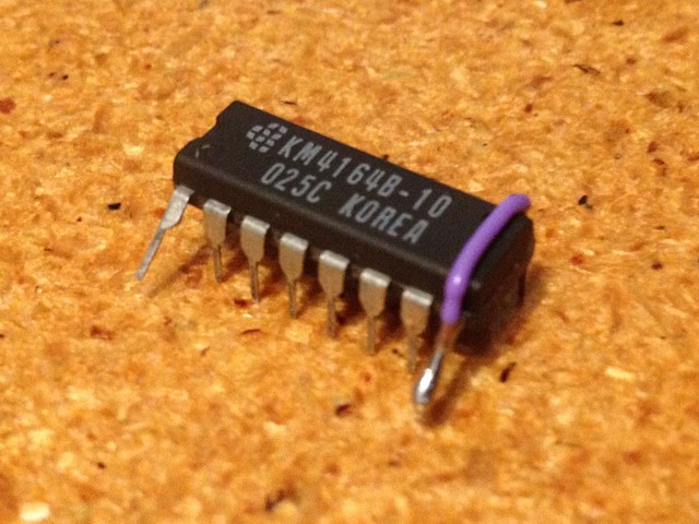
The memory is a single bank of 8 x 4116 Dynamic RAM chips, each being 16k x 1 bit. As all 8 ICs are required to make up every byte of data any failure will be total. Straight away, 1 faulty RAM is indicated by the beep pattern. Fortunately there are still some 4116 IC's available, either New Old Stock or 'pullouts' recovered from old boards - after ordering and receiving a few, removing the one indicated as faulty from location L4, installing a socket and the 'new' IC the RAM test passes.
Note - when the supply of 4116 IC's dries up altogether, it is possible to substitute the more available and slightly more reliable 4164, with a little modification. I did try this while I waited for the 4116s to arrive as I had some 4164s in stock and it worked perfectly. In this case I added a modification to the IC but an entire bank of 4164s could be installed with a slight modification to the PCB.
Although the RAM test now passes, the next part of the diagnostic should be a video display with ROM test etc. which doesn't happen and the RAM test repeats. Leaving 'Test' mode, we still have the flashing screen. At this point the 'blue tearing' screen starts to occur more often and it becomes apparent that it is an intermittent connection of some sort, pressing on the socketed CPU chip especially seems to make a difference and the 'white flashing' screen returns.
Going with first impressions, I replace the 40 pin CPU socket unfortunately without effect. So, tracing the Sync circuit I eventually find some bad solder joints on the 74S74 at position A6 and redo them which fixes the 'blue tearing' fault. With hindsight I realise the sync circuit is pretty much independant of the CPU, replacing its socket was not necessary.
That done, I thought it was time to remove and verify the program ROMS which were all socketed. They all read correctly, unfortunately the pins were very fragile and corroded where they emerge from the body of the IC and bend down - even with great care one pin just broke off completely before I could reinstall them.
I ordered some 2716 EPROMs to take their place, once they arrived I programmed a full set. Though marked with a programming Voltage VPP of 21V, at least with my programmer they failed to program until I selected VPP of 25V (I found some online posts about incorrectly re-marked EPROMS which seemed to match the ones I had just received).
So with all the ROMs replaced, programmed and verified, it was time to see if they were being read, using a logic probe to check their select lines etc. As the board was resetting almost immediately however some of the signals which I would expect to be present when probed weren't occurring, making the fault tracing process a bit misleading.
The ROM3 select line coming from the 74LS139 at position M5 was inactive but replacing that IC made no difference. Similarly, the MADSEL signal was not being generated due to an inactive output from the 74LS10 at position E3 but replacing it also had no effect. Eventually I realised these signals were not present simply because the program was crashing before they were generated.
To test the theory I wrote a little firmware program loop to read every address in turn, which should generate predictable waveforms on the busses and select lines. Sure enough, one half of one of the 2k ROMs was not being selected, causing the original program to crash. This was due to the ROM6 output of the other 74LS139, at position P2 not going fully 'Low'. Luckily the 'Boot Rom' at position R1 was being selected correctly as this is where my little test program was running, as was the original program's RAM test. Replacing the 74LS139 at position P2 fixed the problem.
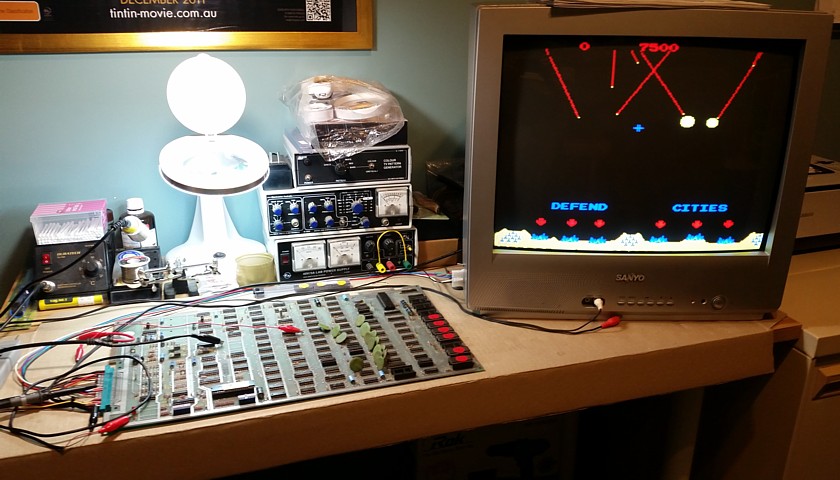
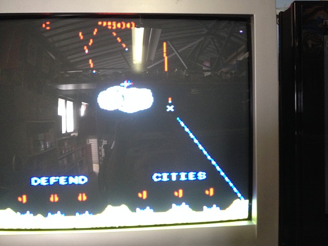
At this point the board is working, terrific! As seen on my RGB Modded Sanyo TV. There are no trackballs or switches wired in so it's time to put it back into the machine to try it out properly.
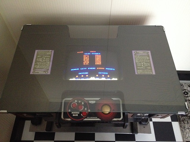
And here it is. Even the monitor has started to behave, though it still needs capacitors replaced and realignment. At this point I started to overhaul the Trackballs, initially taking the Player 2 panel off altogether. The idea is to overhaul the less worn Player 2 controls and swap the entire panel (they're the same) into the main position, then overhaul the one in the picture, touching up the worn paint and put it on the 'back' in Player 2 position.
Unfortunately, after only about a week of occasional operation a secondary fault developed. And yes, I have checked the power supplies to make sure they are not causing new faults to occur! This looks like an issue with the multiplexed data in the video area of RAM, where each Byte of RAM is divided into 4 pairs of 2 bits (i.e. 2 bits per pixel) as there are only 4 possible colours at a time for the main area.
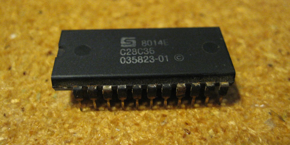
I became suspicious of the chip at location L6 which is a 32 byte PROM, used as a lookup table to control which RAM chips are selected because I had previously noted that it was HOT when running. There were no obvious signs of failure such as data outputs completely missing but if it lost even a single bit of its contents, multiplexed data would not be correctly written to RAM.
Without a readily available replacement or a suitable programmer to create one the best idea seemed to be to test this one first. I carefully desoldered it from the PCB, installing a new socket then made up a simple adapter to the pinout of a 2716 so that my old (made from a kit) EPROM Programmer could read it.
As it turned out it read correctly, verifying against a ROM Dump found online as well as the truth table printed on the circuit diagram. The truth table seems wrong at first but the data bits are actually reversed between the output of this PROM and the bank of RAMs. If the PROM is working but runs hot, the next most likely cause is an excessive load on its outputs, caused by the inputs to the following devices or a short on the PCB somewhere.
With that line of thought I removed the next components in line, a pair of 74S32 ICs at locations L5 and K6, carefully inspecting for bridged tracks, socketing and replacing them. The result - it didn't fix the graphics problem but has it helped the overheating of the PROM? I'll have to wait and see, once the main problem is sorted. If the PROM at L6 does continue to run so hot, I'm inclined to add a little self adhesive heatsink at the very least.
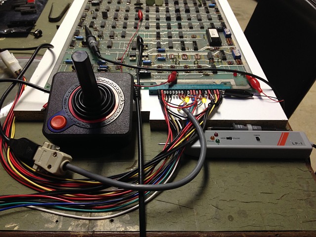
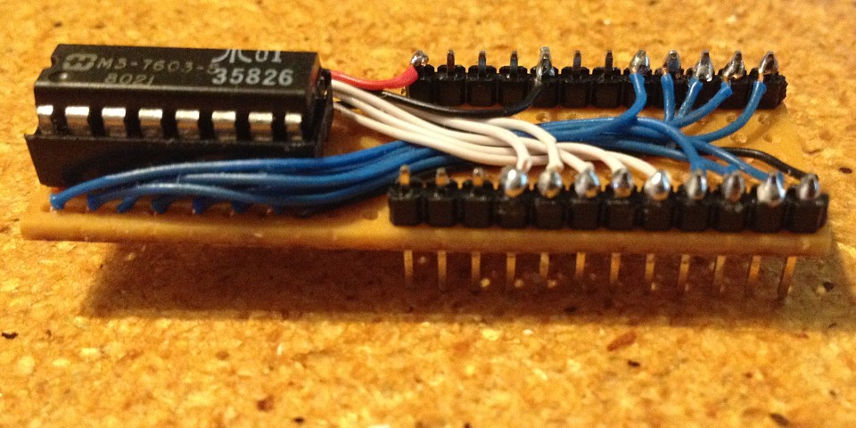
To diagnose the graphics problem it will help to select one of the stationary test patterns available from within Test Mode - by pressing the 'Slam' switch in conjunction with one of the three fire buttons. I considered making a little test panel with switches before realising I already had something I could use - the original Atari 2600 Joystick, effectively five switches in a box. I've wired the 'Slam' switch input to the red button and the three fire inputs to left, up and right on the joystick. While I was at it I wired 2 Player start to 'down'. I've also wired two yellow LEDs to the Player 1 and 2 Start button LED outputs on the edge connector.
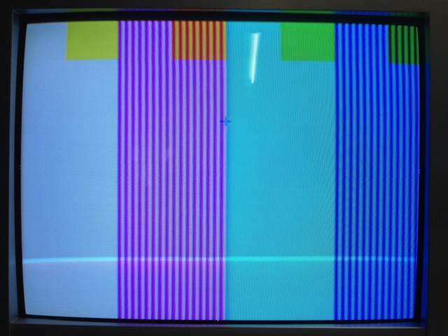
This pattern should just be four bars in the main area; White, Magenta, Cyan and Blue with Yellow, Red, Green and Black also displayed in the 'cities' area which is at the top as the pattern is showing in flip screen mode for some reason.
The White, Yellow, Cyan and Green areas are unaffected while the Magenta, Red, Blue and Black areas are alternating between the correct colour and the 'wrong' colour which is obtained by adding Green in each case. The colours which are unaffected contain green anyway.
So there is a bit error but which bit? That actually depends upon the colour palette which has been loaded into the 'Color RAM' at location L7, by the software. It must be one of the two main colour bits and not the third colour bit which only affects the cities area.
Counting the strips, there are 8 red and 8 yellow in that small segment (so 16) in 1/8th of the screen width so there would be 128 strips across the screen. The Horizontal resolution of Missile Command is 256 so there must be 2 pixels which are correct followed by two which are wrong, etc.
For the 2 bit colour area, each byte of RAM contains 4 pixels of data. The upper and lower 'nibbles' are latched into two 74LS195 4 bit shift registers at locations N7 and M6 and shifted out by the 5MHz clock signal.
So if one bit from the RAM was wrong we would expect only every fourth pixel to be affected. If one whole byte of RAM was wrong that would affect 4 pixels each error. As this fault is 2 right, 2 wrong it could be one of the DRAM Data Input Selectors, which could affect 2 adjacent bits of data but as the initial RAM test passed I think we are more likely to have a shift register issue.
Attempting to confirm this, I looked at the outputs of the shift registers while the test pattern was being displayed, using an oscilloscope and observed the toggling output on the 74LS195 at position M6. (The top trace is HSync.) Looking at its inputs they were as expected for a stationary pattern, changing only at 1/4 screen width intervals so I was confident enough to order some 74LS195 IC's and put the board aside till they arrived.
Now, in a case of 'One Step Forward and Two Back' powering the board up after a month or two, it won't start at all. It seems to have developed (yet another!) new fault. The RAM test fails but this time changing the RAM chip in question at location H4 doesn't correct the problem. Checking its inputs and outputs there is no data arriving or leaving so, tracing back through the Data Input Selector to the 74LS244 at position E2 there is no Buffered Data bit 1 output. It looks as if the 74LS244 has failed, this must be corrected before we can get back to the video problem.
So the parts have arrived and firstly, socketing and replacing the 74LS244 at position E2 has corrected the missing Buffered Data bit and resulting RAM error. The board is up and running again, still with the graphics issue.
Now replacing the 74LS195 at position M6, cures the graphics problem as predicted. As seen, this time on my RGB Modded NEC TV. We're back to a working PCB, can return it to the machine and get back to overhauling the control panels next!

But what about the overheating PROM at L6? I hear you ask. Well, I'm pleased to report after several hours of running to test out the repairs, the PROM is no longer hot to touch. It appears the little side track to investigate that observation was not wasted effort and may well have prevented the imminent failure of another (not readily available) component.
My Taito Missile Command TT has been on the back burner while I've worked on some other arcade machine projects. I'd returned the repaired PCB to the machine but was unable to fully test it while both control panels were removed for overhaul.
Having thus far finished tidying up the original Player 2 panel and refitting it in the main, Player 1 position I found the trackball vertical axis was no longer working. After checking the positioning of the opto couple and tracing the signals from there it turned out one gate of the MC14584 Hex Schmitt Trigger inverter (in position C9 on the PCB) had a dead output.
Searching for readily available replacements I found a Toshiba equivalent to the Motorola original component, the TC4584. After ordering and receiving a few, installing one with a new socket and testing, the trackball is now working well again.
Now I just need to overhaul and touch up the original Player 1 control panel, to be refitted on the 'back' of the machine in Player 2 position.
I've set myself a challenge to finish off all of my arcade machine projects, although most are working to some extent a lot of finishing touches are needed to return the machines to 'fully working' condition.
My Taito Missile Command TT cocktail machine is no exception, having repaired the game board some time ago I need to overhaul its monitor as well as completing an overhaul and tidy up of its two control panels.
I'd reached an impasse with the Taito manufactured mini trackballs which were quite worn and it seems no reproduction parts were available to suit. Although similar to the Atari Mini Trak ball which has reproduction parts readily available those are sadly not interchangeable with the Taito units.
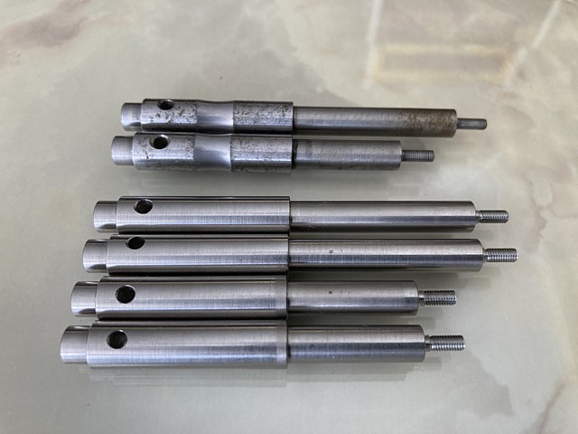
Having exhausted all other options the way forward was to have some new reproduction parts made. These two sets are the prototypes, seen here with two original worn shafts. Although the smooth curves worn into the old shafts look like they're meant to be there the shafts are actually dead straight when new.
The wear pattern increases friction resulting in a sluggish control movement also increasing the gap between the ball and control panel which causes a risk of pinching when operating the trackball. Apart from the shafts I've amassed a new set of bearings and new 2 1/4" (yellow) pool balls to suit.
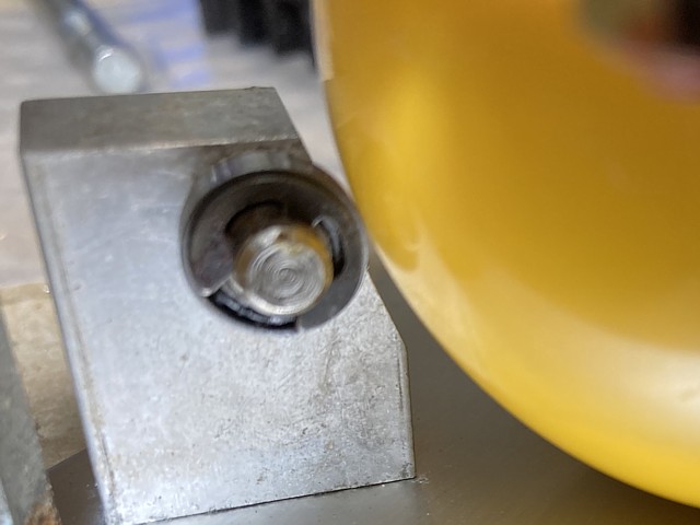
Dismantling and reassembling the trackball mechanism with new bearings, shafts and ball is straightforward except for one of the flanged bearings which is mounted into a blind hole and can't be pressed out from the other side. To avoid damage trying to pry it out by tapping a screwdriver or blade beind the flange it's safer to push it out with hydraulic pressure.

A useful trick when working on cars it can also be done on a smaller scale here. First pack the entire space with grease, using the old shaft as a tamper to push it into the recess and expel all of the air. Once the shaft encounters resistance and can't be easily pushed into the centre of the bearing, a few taps with a hammer will compress the grease and push the bearing outwards.
I slipped a small socket bit over the threaded end of the shaft to avoid any damage when tapping with a hammer. Once the bearing is pushed outwards enough to place a couple of screwdriver tips behind its flange it can easily be levered out fully.
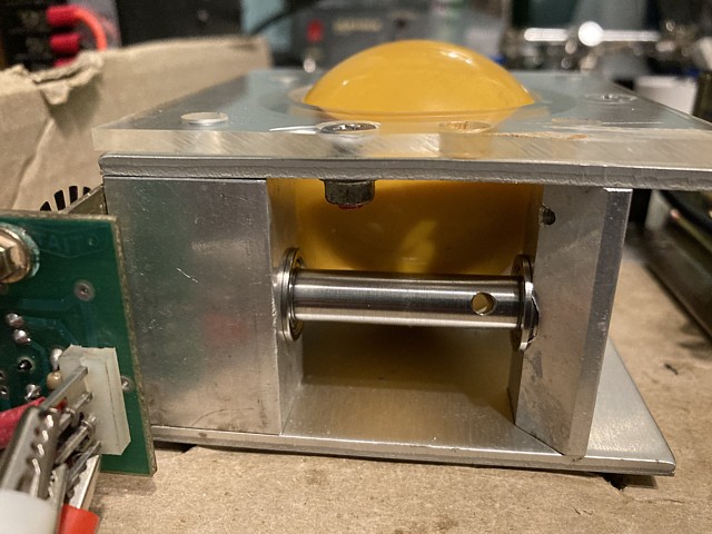
The new ball, shafts and bearings assembled into the mechanism. The flanged bearings are sealed both sides and pre-packed with grease requiring no extra lubrication. Eventually a narrow contact area will wear into the shafts but the stainless steel tends to harden with work and will resist excessive wear. These ones should last a lifetime especially now the machine is not operated commercially.
As well as the four shaft bearings there is one tiny bearing at the opposite corner to keep the ball in contact with the two shafts. This one is barely larger than the circlip which retains it and not sealed so needed to be greased and the excess carefully removed to prevent any transferring to the ball and from there to the shafts. The sealed version of this bearing is slightly wider so would not fit.
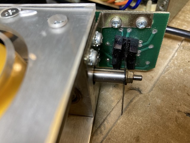
An unusual feature of the Taito trackball (or at least the one fitted to this machine) is the optical sensors being the curved type even though the slotted disc is flat. I suspect these little boards are the same as used on Taito's Arkanoid spinner control. It seems to me using a curved optical assembly makes the adjustment process more critical as the distance between the two beams varies and needs to be matched with the spacing of the slots of the disc.
Normally just done in the machine by trial and error, it's not usually possible to see the exact relationship between the two signals, one normally labelled 'clock' and the other 'direction'
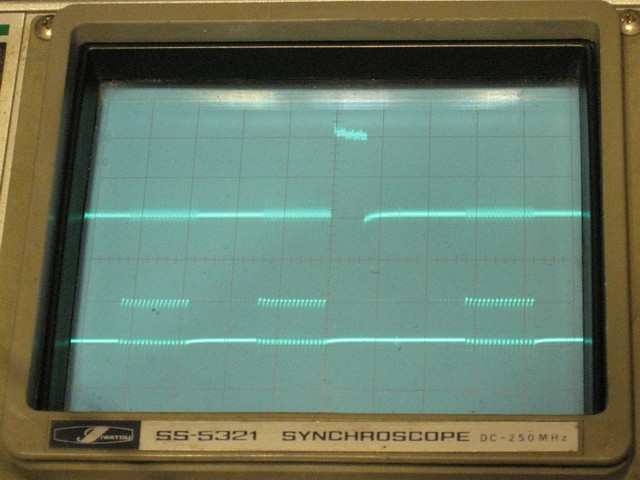
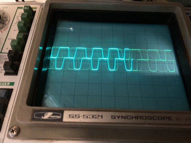
To demonstrate I'm setting the trackball up on the test bench to be viewed with a dual trace oscilloscope. To view the two outputs from one axis at a time it's just necessary to provide +5V and ground, also adding a 10k Ohm resistor from each output to ground. The trackball needs to be moved fairly briskly, at the same time taking a photo as this analog oscilloscope has no storage capacity.
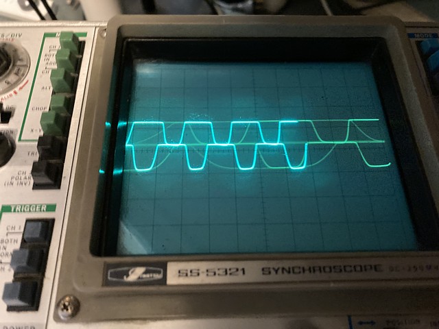
The initial photo above looks lovely and symmetrical, the two approximately square wave signals being almost exactly 180 degrees apart, one high while the other is low. But that's a problem and won't work. Turning the ball in either direction would produce much the same result with no way to detect the direction of movement.
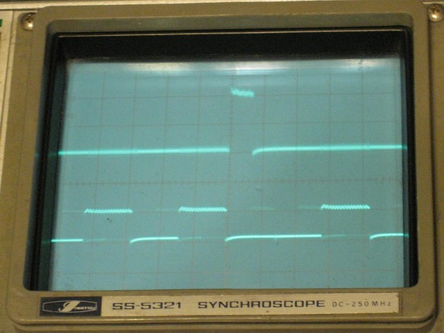
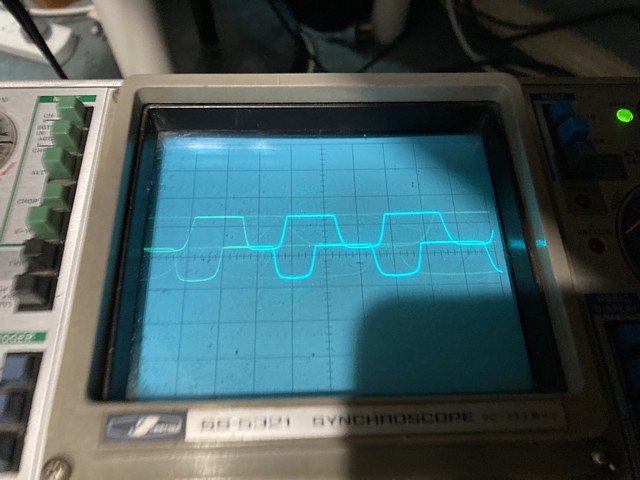
To allow the speed as well as direction to be determined, the two signals need to be bi-phase, 90 degrees or one half of one slot difference in the timing of the two signals.
Adjusting the position of the sensor now so the slotted disc is much closer to the convex side of the sensor and not in the middle of the slot, the relative phase of the two signals looks more correct. If we look at just the rising edge of the two outputs we can see the lower trace changes from low to high near the middle of the 'high' period of the upper trace.
This gives a clue to the way a trackball axis or spinner signal is decoded within the game PCB. The speed can be calculated easily enough by arranging a counter to determine the period between one cycle and the next. To determine direction, we just need to see if the second signal is leading or lagging behind the first.
Just looking at say, the rising edge of each signal, turn the ball one way and this occurs later on the lower trace compared to the upper (as above). Turn the ball the other way (as below) and the rising edge of the lower trace now occurs earlier than the upper trace.
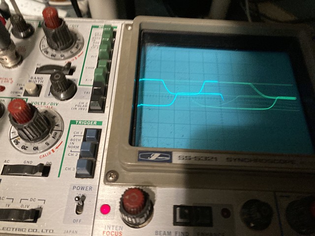
To determine this electronically we can use a latch which is triggered by an edge of the first signal (clock) At that moment the instantaneous level of the second signal is entered into the latch (i.e. direction) In the first example when the rising edge of the first signal occurs the second signal is low. In the second example the result is high. This allows us to determine the direction of movement in addition to speed.
Incidentally, the two signals are interchangeable, swapping the wires between them merely reverses the direction of the control.
To be continued...
Web Resources (External Links) -
The Arcade Flyer Archive - Video Game Flyers: Missile Command, Taito
Missile Command table by Taito! - YouTube
A-Z of Missile Command w/ Tony Temple | Free Play Florida 2018 - YouTube
Atari's 1980 classic "Missile Command" arcade game.. gameplay, artwork review, great game! - YouTube
All images and text on this website are Copyright.
Contact: jbtech at telstra dot com