Arcade Monitor Test Rig
Caution, CRT TV's and monitors have dangerous voltages, even when switched off. Please don't take any risks and don't work on them at all if you are not familiar. Always safely discharge the High Tension from the CRT before performing any work. Many older TV's and monitors have a 'Live Chassis' and must be used with an isolation and / or stepdown transformer and not connected directly to the mains.
Updated 17/2/21
One of the most important components and probably the most troublesome - in any original style arcade machine is the CRT (Cathode Ray Tube) monitor. Now obsolete and no longer manufactured, surviving examples need increasingly frequent attention as worn and ageing components become a major factor affecting reliability.
It's difficult to work on the monitor, removing and returning the chassis to the machine at each stage. While some (particularly U.S. manufactured) displays have a frame which unites the CRT and Chassis, many examples in use here have the chassis and tube separately mounted into the machine, making them difficult to set up on the test bench.
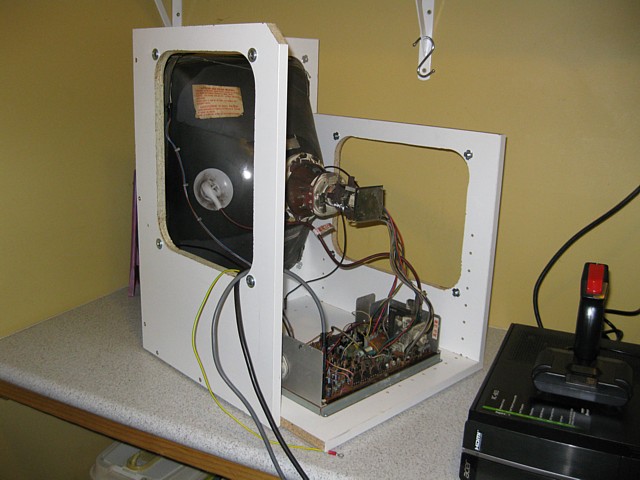
The solution is a simple test rig which supports a CRT and chassis allowing them to be safely connected and tested outside of the machine, also providing suitable power and video signals to make it work.
The frame is for bench top use, three sided and fairly open to allow ease of access for testing. To keep dimensions to a minimum a 20" CRT can be mounted with vertical orientation, or a 14" CRT mounted either way using the side openings while the chassis under test is securely fixed to the base.
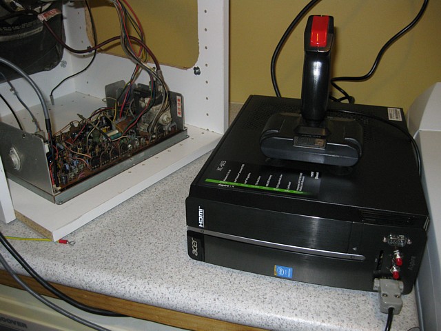
To keep the test area safe and uncluttered the mains isolation / stepdown transformer, multi game PCB (used to generate a video image) and its power supply are all fitted within a repurposed compact desktop computer case.
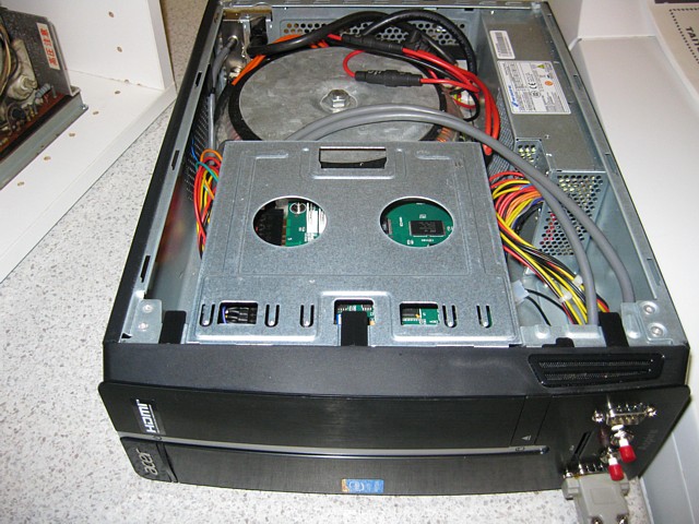
Inside the case the main area is taken up by the transformer while the game PCB resides in the space previously occupied by the computer's DVD drive. The original compact ATX type power supply is retained to power the game PCB.
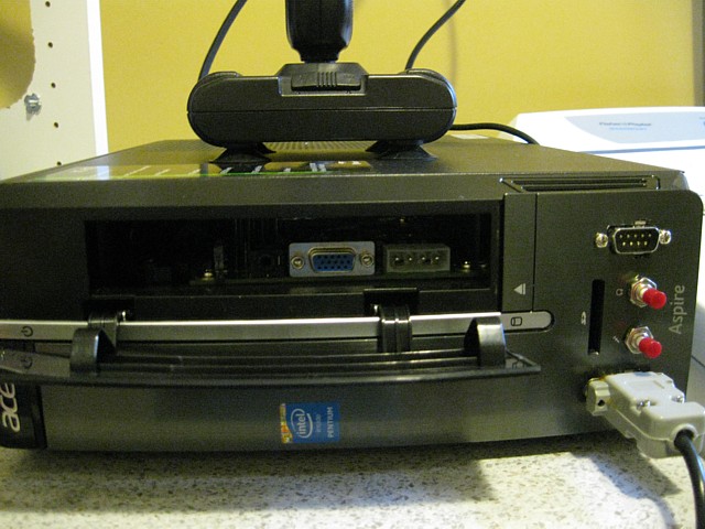
Cables for Monitor power and the Standard Resolution RGBs video signal exit via the rear panel. The VGA and audio outputs from the game PCB are also accessible if required, behind the original DVD flap.
The front panel now has two DB9 connectors for Atari / C64 joysticks and 1 Player / 2 Player start buttons. To save the need for a coin switch or credit button the game PCB is set for free play and there is a miniature speaker from a laptop fitted within the case so the menu and game sounds can be heard.
The power transformer has a rear panel switch and fuses on primary and secondary while the separate ATX power supply now has a toggle switch for Power On / Standby . The game board can be set to display a test pattern and setup menu by pressing the PCs original power button (now Test switch) as the board is powered on.
All images and text on this website are Copyright.
Contact: jbtech at telstra dot com