RGB Modded NEC TV
Caution, CRT TV's and monitors have dangerous voltages, even when switched off. Please don't take any risks and don't work on them at all if you are not familiar. Always safely discharge the High Tension from the CRT before performing any work. Many older TV's and monitors have a 'Live Chassis' and must be used with an isolation and / or stepdown transformer and not connected directly to the mains.
Updated 14/8/20
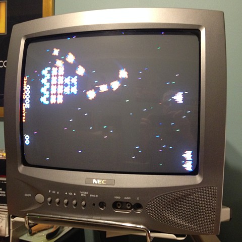
This is another TV which can be modified to accept RGB signals from a console or Arcade PCB. It's a 34cm NEC which I bought new 15 or more years ago. It's had only occasional use and is in great working condition but only had an AV (Composite Video) input in addition to the Analog TV tuner.
The 51cm Sanyo TV which I've already modified is working well but takes up too much space on the test bench. I'd like to set up this more compact unit on a desk-mounted monitor arm to free up some space and get caught up with my backlog of arcade PCB repairs. Let's see, there's the Missile Command (again), Space Invaders colour, Golden Tee Fore, of course and now the Challenge pong to do.
At first glance, the TV seems a likely prospect for modification as the AV input panel on the back has the outline of a SCART connector. Obviously there was a version of the same TV which had a RGB SCART input so the signal processing hardware should have the capability at least.
It's not as easy as adding a new socket, though. As this is a 'stripped down' version the manufacturer will have left off any bits which were not required to display only Composite Video. The PCB looks like the full version as there are solder pads to install the SCART connector but there are a few spaces and empty holes where some features have obviously been omitted.
The first step is to find a circuit diagram. Searching on the TV Model Number yields only a copy of the user manual (useless manual, in this case.). Looking deeper, there is a Part Number label on the PCB. Searching this reveals the TV (or the chassis at least) was actually made by Daewoo. It turns out the brand is also moulded into the inside of the back cover so that should have been another clue.
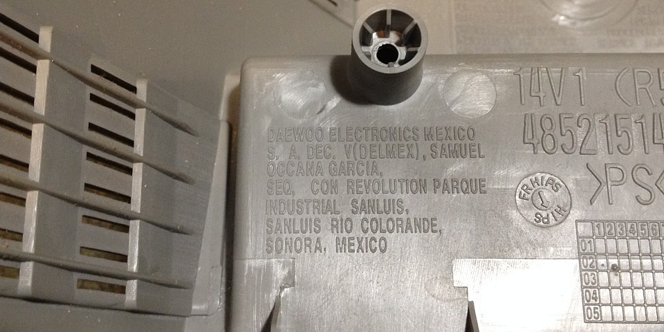
I found a copy of the service manual online, for a Daewoo model with the nearest match to my NEC TV's PCB number. Perfect, as it turns out the Daewoo circuit diagram includes all the necessary circuitry for the RGB input. With a bit of luck, adding all the omitted components as well as a new socket will do the trick.
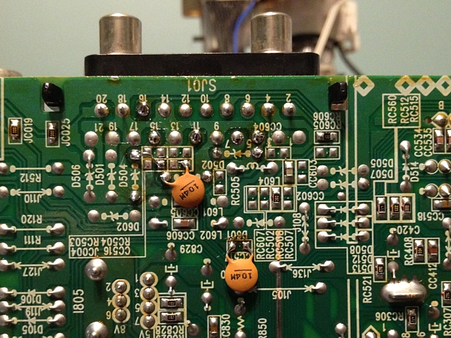
Starting at the input, there are three missing 75 Ohm (surface mount) terminating resistors, paralleled with (through-hole) zener protection diodes so the through-hole pads can be used to save ordering surface mount components. Likewise, there's a jumper link needed - a little loop of wire saves ordering a zero ohm surface mount resistor. Two ceramic coupling capacitors can be soldered on the underside of the PCB in place of the missing chip capacitors.
If this modification was for a customer order I'd be sure to use the original spec. components but for my own workshop use there is no need to reproduce the factory finish - in fact I'd rather be able to see what's been changed.
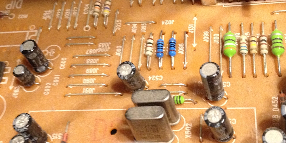
Tracing the path towards the signal processing IC, there were two more resistors and a wire link omitted. The wire links are not shown on the circuit diagram but necessary where any PCB track must cross another track on the single-sided PCB.
With the signal path now reinstated it just remains to add a connector (I'm using the same Mini-Molex format as I've used before, which my existing test-cables are wired to suit) and take care of the switching. In the SCART standard, to switch from the Composite input to RGB, a small voltage must be applied to pin 16, usually supplied by the connected equipment. Here I'm using the TV's internal 5V rail, via a rear panel mounted switch and a 180 Ohm resistor, wired to the PCB pad which would correspond to Pin 16 on the SCART connector.
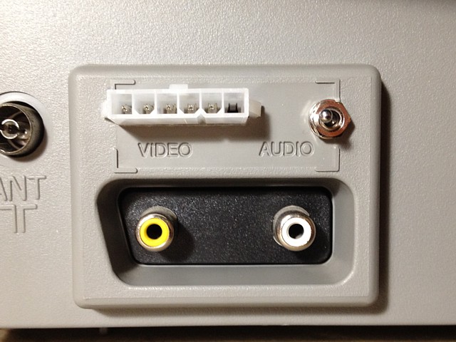
It should be possible to install a PCB mounted SCART connector here instead of the 2 x RCA sockets, as per the original Daewoo version but for workshop use that's not necessary, just adding the Mini Molex connector (and a switch) suits me better.
All images and text on this website are Copyright.
Contact: jbtech at telstra dot com