
Ohio Scientific Superboard II reproduction
I bought my first computer in 1980 when I was still in high school, with money saved up from weekend work. It was an Ohio Scientific Superboard II, model OSI 600. For me this was a defining moment.
1980 was the first year schools in my region offered any class directly related to computing. It was called 'an Introduction to Computer Science' and mainly concentrated on programming in BASIC. With just a single computer for the entire class to type in and test run their program assignments the pace was limited by access to this mysterious device. It was an unknown model with some early 8 bit processor possibly an 8080 or maybe even a 2650, BASIC in ROM and 8k Bytes of RAM.
Probably the result of a government tender for supply of computer equipment for education, it looked like it had been cobbled together by some local engineering firm rather than mass produced. At least it would have been locally made. Program storage was by audio cassette and there was a tiny printer for program listings. That was a sort of electrostatic device which printed onto rolls of metallised paper about the width of a modern cash register docket. The printed text looked like blackened dots on a silver - grey paper background.
As limited as this now seems it opened my eyes to the world of digital electronics, logic and programming. I was already interested in electronics and had built a number of projects, mostly from kits. I was also fascinated by the technology behind early video arcade games such as Space Invaders which really did seem space age to me at the time. Needless to say I took to the computer class with great enthusiasm and very soon needed a system which I could learn on in my own time.
Somehow I found an advertisement (possibly in the local newspaper) by a newsagent and stationer who had branched out into selling home computers, for the Ohio Superboard II. The Superboard was significant as it was a complete system on a single board requiring only a black and white TV monitor and standard cassette recorder for program storage - and a 5V power supply which was not included.
The fact that it was just a printed circuit board with no case or power supply didn't worry me in the least having built a number of small PCB projects and even making cases for some of them in woodwork class. At a slightly higher price the OSI 600 could be bought as a finished product in a case with internal power supply, known as the Challenger 1 but the Superboard at around A$300 was just within my budget at the time.
Besides in those days computers such as this were for experimenters and engineers alike, being sold with complete circuit diagrams and technical information encouraging and even leaving unused spaces on the PCB for customisation - unlike the pre-packaged and proprietary consumer products of today.
The Superboard II had a 6502 CPU which was clocked at just under 1 MHz, 8k Bytes of BASIC in ROM by some company called Micro Soft and in standard form was loaded with 4k Bytes of RAM with space on board to expand that to 8k Bytes. Having only 4k of program memory to work with was a definite learning experience; finding ways to write programs which were economical on storage and ran efficiently with minimal resources. Modern programmers would do well to take a step back and re learn these attributes!
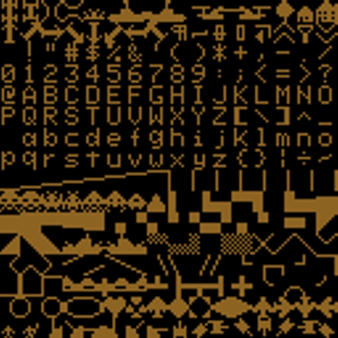
In addition to the usual alpha numerics the Superboard's character set included many graphical figures such as tanks, spaceships as well as geometric shapes. I soon learned how to place these on screen and move them around using the BASIC POKE command, writing a number of games with titles such as Road Race, Tank Battle and inevitably the one which was my final project for the school computer subject, a tribute to the current arcade sensation - Space Invaders.
Admittedly the graphics didn't scroll smoothly like the arcade original, the figures just jumping one character column or row at a time but it was immediately recognisable and quite playable. I wrote it for the Ohio character set and screen map initially, using every trick I had learned to save space such as combining multiple commands onto a single line (a colon using fewer bytes than an additional line number) etc. then adapted it to run on the school computer.
Having taken every imaginable shortcut to optimise the game speed on my computer such as moving each invader one at a time before jumping back to update laser base and missile positions it played quite smoothly. Unfortunately the school computer turned out to be much slower so the game play was a bit jerky on that machine but it was well received all the same. There is no question that I learned so much with the benefit of my own computer at home to experiment with, something that most people take for granted today.
I never did expand the RAM to 8k Byte or increase the clock speed to 2MHz (another popular mod and easy to achieve on the Superboard) but it did gain a case (in fact two different cases) along the way. The first case was timber with plywood panel cut out for the keyboard and covered in gloss white laminate. The Superboard being totally flat defined the shape of the case which looked much like the Challenger 1. The power supply was still external, housed in a metal box.
Eventually I replaced that case with a metal one which had originally housed a keyboard for an electro mechanical paper tape punch. These were being phased out at the time and surplus ones dismantled for spare parts so I was able to have the empty case for free. It was heavy gauge steel, I made the keyboard panel from aluminium and painted it white and grey rather than its original industrial shade of blue.
This scan from a photo taken around 1988 is the only one I can find of my original Superboard, seen in its final shape and form. To align the keyboard with the slope of the case the entire PCB was mounted inside on an incline and the power supply built in to the base at the back. The case is obviously quite a bit wider than the Superboard PCB as you can see I added a numeric keypad repurposed from a desktop calculator, wired in parallel to the numeric keys.
Just visible in the photo is a pair of joysticks which I had begun installing into the front panel just above the keyboard, giving the machine a slightly Dalek-like appearance. They were analog ones with potentiometers but the intention was to convert them to switch closures so they could also be wired in to the existing keyboard and operate in the same way as key presses. That's as far as I got with the Superboard, eventually it was sidelined as IBM compatible machines with MS-DOS, floppy and hard disk drives became commonplace.
Sadly, the Superboard stopped working at some point and was eventually discarded to free up space for newer machines and projects, its large and heavy case became its downfall. Technology was advancing so rapidly at the time that previous generation machines seemed irrelevant, their incredible significance unappreciated until recent times. With a renewed interest in earlier technology I have searched online for surviving examples of the Superboard from time to time but never came across another one which was within reach.
Looking again just recently I appear to have missed any chance at finding an original one for sale. Very few seem to have come to Australia to begin with, the survivors having mostly found their way into museums or already snapped up by collectors. Thanks to the efforts of some OSI and Vintage Computer enthusiasts however there is another possibility, to assemble a reproduction of the original Ohio Superboard II using a brand new PCB and mostly original components.
Ohio Scientific were trailblazers in the micro computer field in the late '70s to early '80s and the definitive resource for information on the systems they produced is Dave's OSI Repository at www.osiweb.org. Thanks to its many contributors the site hosts an archive of documentation for several systems produced by Ohio Scientific during their brief corporate history. One contributor of note, Grant Klyball ( klyball.com ) has faithfully recreated the OSI 600 Superboard II PCB layout as well as the 610 expansion board and kindly shared those on the osiweb site.
My sincere thanks to Grant for his outstanding feat in recreating the Superboard PCB so perfectly and Dave for keeping the history of Ohio Scientific alive for enthusiasts around the world like myself. So having finally abandoned hope of picking up an original Superboard I've resolved to build a replica using the Klyball 600 PCB design and sourcing the components to complete the build. This takes me back to my very early days experimenting in electronics and building kits.
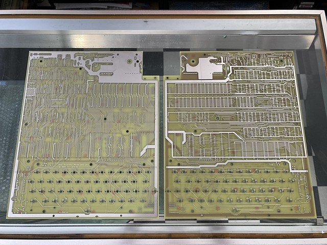
To begin with I've sent the PCB files off to have a small batch produced. That turned out to be a learning experience in itself, like many late '70s products the OSI PCB had no solder mask originally, the entire copper area being tinned. This does require care when assembling to avoid shorted tracks and also caused some concern by the PCB manufacturer who are accustomed to producing modern, high volume PCBs to the latest precision standards.
Initially the PCB files bounced in pre production audit - the solder mask layers are missing, please correct. I responded there was no intended solder mask so they asked if I just wanted the copper completely covered by HASL? Doing a bit of reading, HASL stands for Hot Air Solder Levelling; after solder mask is usually applied any still exposed copper areas are tinned in a sort of wave soldering process then the boards are hit with hot air to smooth the soldered area. Yes, thanks that's exactly what I would like was my reply.
Then came the caution, there will be some risk of shorted tracks - I assume they mean during production not only during assembly - was that OK? Yes, I assured them I would take that chance. Then they came back and asked wouldn't I prefer an ENIG surface treatment? More reading and ENIG stands for Electroless Nickel Immersion Gold and instead of tinning the copper tracks a fine layer of nickel is deposited followed by a dip in gold which is ideal for surface mount and precision assembly and would also reduce the likelihood of shorted tracks.
Imagine the cost of nickel coating the entire copper area on these boards (which are over a foot square, in the old money and double sided) then dipping them in gold! Besides, that would be nothing like the original '70s finish. No thanks, I replied, HASL will be fine.
Now we were getting close but the Klyball design did include a silk screen layer with some component outlines and that was another issue. Apparently the normal procedure is to etch the tracks then apply solder mask then silk screen then HASL so without any solder mask the silk screen would be applied directly over the copper and destroyed during the HASL process - so that was not possible. I have seen older PCBs with no solder mask, these were usually silk screened after being tinned but that apparently doesn't fit in with the current production process.
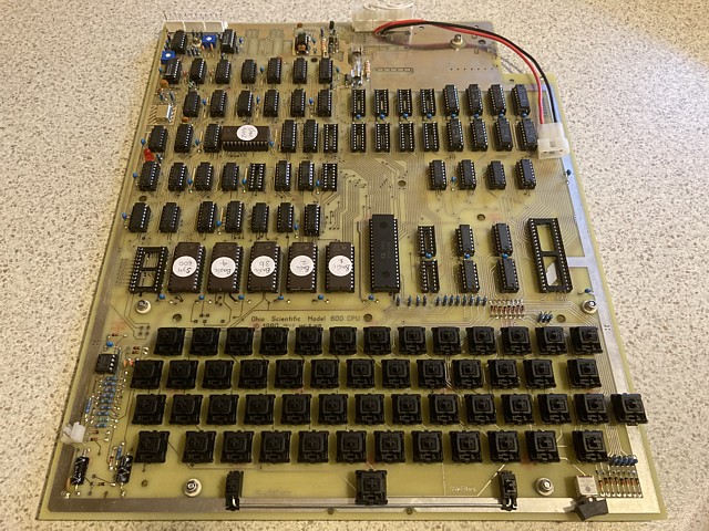
In any case the original Ohio Superboard PCB had no silk screening at all so the simple answer was Yes, please just leave the silk screening off. Having made those choices the PCBs sailed through production and arrived very soon afterwards and they look fantastic. Just the look of the unpopulated PCBs and their outline is bringing back memories of my original Superboard.
There is no urgency to complete this project and I am sure it will take some time to source the components as some are obsolete and can only be bought as old stock. Thankfully Grant addressed the issue of non available original keyboard switches in his design, adapting the layout to accept modern day Cherry MX key switches commonly used in mechanical, gaming keyboards. Likewise he incorporated a minor adjustment to the pinout of the 24 pin sockets to accept 2716 EPROMs in place of the original ROMs.
I believe at one point a small batch of reproduction key caps were commissioned by someone, to suit the new key switches with the original style lettering and layout but suspect these were all spoken for some time ago. I may just begin with an 'off the shelf' set of keycaps if a full custom set is beyond the budget, in fact I've been considering the option of using a compatible gaming keyboard as a donor for key switches and caps as a possible way to reduce cost and keep the project more in line with the original intent of a low price computer for experimenters...
I've begun assembling a reproduction of the first computer I owned, the Ohio Superboard II from 1980. This reminds me of previous projects which I've assembled from kits except in this case I'm having to source all of the components separately including the PCB itself. Fortunately there is a complete set of assembly instructions available.
Though my original Superboard was bought as a complete PCB needing only a power supply and TV monitor to operate, the model was eventually sold in kit form so I'm following the assembly manual which was issued in 1982 after Ohio Scientific was bought out by M/A Com.
A very similar computer known as the Compukit UK101 was also released in kit form, this was apparently a non authorised clone of the Ohio Superboard which originated in the U.K and featured some enhancements. Although similar to the Superboard the two computers are not identical, some UK101 kits may have made it to Australia at the time but I have never seen one.
The assembly procedure begins with IC sockets followed by small components such as diodes, resistors and capacitors. I have many of these on hand to begin with and can source the few remaining passive components locally. Meanwhile I have some of the TTL ICs as well as the CPU and EPROMs but will need to order the remainder including a number of obsolete types and wait for them to arrive.
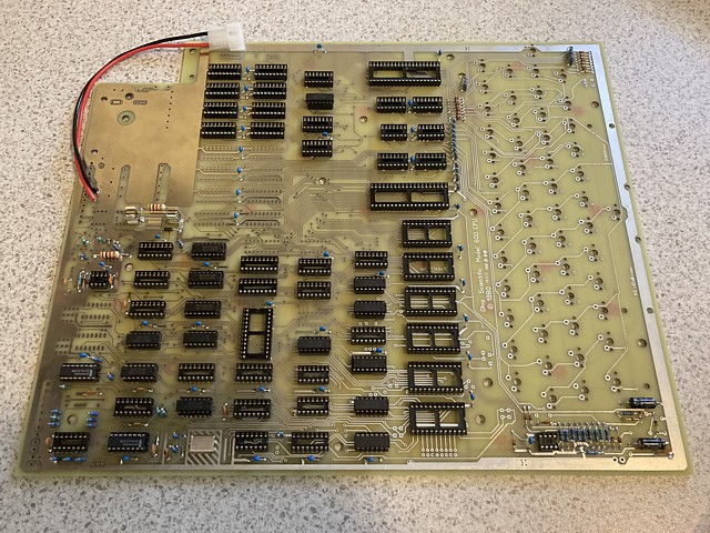
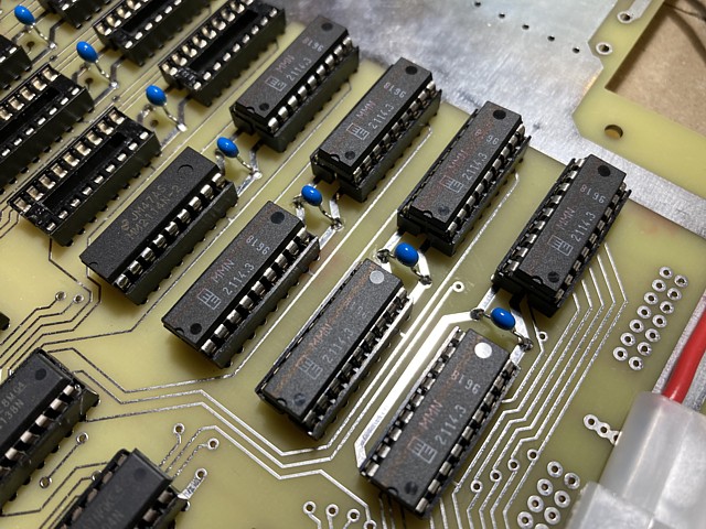
The Ohio Superboard II reproduction is coming along, I now have almost all of the major components with the exception of the key switches and caps - and a couple of hard to source obsolete ICs which are on order but yet to arrive from overseas suppliers. All of the IC sockets which are normally present on the Rev. D PCB have now been installed and the full complement of TTL ICs fitted.
The discrete semiconductors and passive components are also installed with the exception of a single 47uF axial electrolytic capacitor which remains outstanding from a previous order. If that item doesn't arrive soon I will substitute a 100uF axial which I have to hand and will work equally well in this application.
Also on hand but yet to be fitted are the 6502A CPU, 6 x 2716 EPROMs and 10 x 2114 RAM ICs (4k Bytes of program memory plus 1k Byte of Video RAM). Yet to be received are the 6850 ACIA port and 2 x 8T28 buffer ICs.
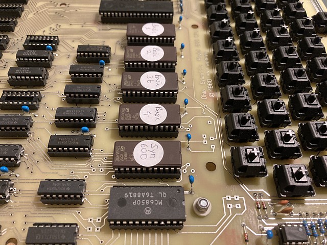
Here I'm using my PC controlled EPROM programmer to install the firmware ROM files into the 2716 EPROMs. The Klyball PCB reproduction incorporates a minor modification to support 2716 EPROMs in place of the 9316 type ROMs which would have been used in the original.
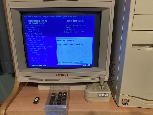
The files I'm programming into the EPROMs are; the original Syn600 monitor ROM which contains the bootup routine and machine code editor program, Basic ROMs 1 to 4, each 2kByte to contain the 8k OSI Basic in ROM - in this instance Basic ROM 3 is the 'patched' version which corrects a known bug in the original so I'm labelling that one 'Basic 3b' - and the Character Generator ROM.
I've done a small 'hack' to the Character Generator ROM file, editing some of the content to include a set of 'Space Invaders' inspired characters. These differ slightly from the Taito originals, being only 8 x 8 pixels to fit within a single character space while the Taito graphics each occupied two bytes wide by 8 high.
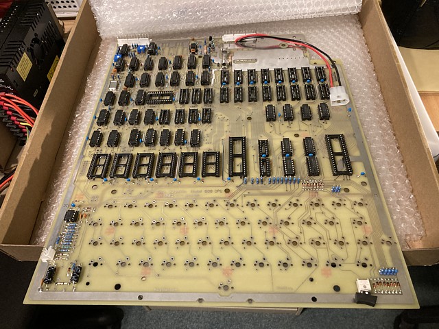
A little more progress with the Ohio Superboard II reproduction, the 8T28 buffer ICs have arrived but the 6850 ACIA ICs which I ordered some time ago appear to be stuck in the postal system. I've installed the buffers, EPROMs and CPU to their respective sockets on the PCB.
Meanwhile I conceded the effort to desolder and remove 53 key switches and caps from a donor keyboard would be too great and the results less than satisfactory as some of the Ohio keycap sizes and legends don't match up with modern keyboard layouts.
Instead I've ordered, received and fitted new Cherry MX key switches, these ones are the basic 'black' type MX1A-11NW with a linear, not clicky action. I also managed to source a levelling mechanism for the spacebar with the correct mounting arrangement and spacing, that one has type number G99-0744.
I'll try to obtain a set of reproduction keycaps for the Superboard if possible. It may also be necessary to substitute a higher force key switch for the spacebar to compensate for its extra weight and friction of the levelling mechanism, we'll wait and see.
In this update we'll get the Ohio Superboard II reproduction up and running, sort out any issues with the build and even add a couple of minor modifications. 'Hacking' or adding hardware modifications was common practice back in the day and the Superboard, being simple and well documented lent itself to experimentation.
In this instance the intention is to recreate the original Ohio Superboard experience and not to 'hot rod' the board with increased capacity or performance, I'm just adapting the external connections slightly to fit in with the more modern peripherals I have to hand. More on that later.
Apart from not having any key caps as yet the only missing item was the 6850 ACIA (Asynchronous Communications Interface Adapter = serial port) IC which never arrived from order and appears to be lost in the postal system.
It wasn't an expensive part and I could reorder but the lead time would be an issue so, hunting through my old spare PCBs I've found one which I can desolder and reuse. Unfortunately in my haste I've broken one of its pins (should have taken more care) so I'm just repairing that by soldering another leg cut from a faulty IC onto the stub of the broken leg.
Eventually I'll replace it with a new part but it should be fine for testing so, cleaning up the traces of solder from the IC legs and placing it in the waiting 24 pin IC socket the Superboard is ready to power on.
Initially I'm using my bench power supply which has an adjustable current limit with meters to show the Voltage and current drawn, also connecting the Superboard's monochrome composite Video output to the 14" NEC colour TV video monitor which I use on the bench for testing arcade PCB repairs. Powering on I see a faint image with the letters 'H / D / M ?' near the top of screen.
That's not quite as expected, the familiar startup prompt should read 'D / C / W / M ?' and be located near the bottom of screen. Also there is no response when any of the keys are pressed. Initially thinking there may be some memory error causing the incorrect text and placement, I soon realise the monitor ROM file which I've used was not the correct SYN600 version for the Challenger 1 / Superboard II.
That would also explain the lack of keyboard response as some other Ohio Scientific products used a serial rather than polled keyboard. Locating another copy of the SYN600 ROM file from a different source, erasing and reprogramming the 2716 EPROM gets us back on track.
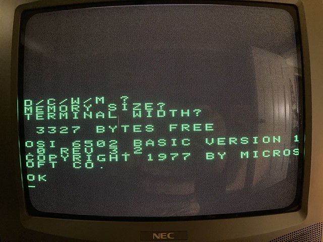
Powering on again and seeing the correct prompt - still a little faint on screen but we'll worry about that later - finding the C key and then pressing RETURN for 'Memory Size' and 'Terminal Width' prompts, the familiar startup message displays but the available memory seems incorrect.
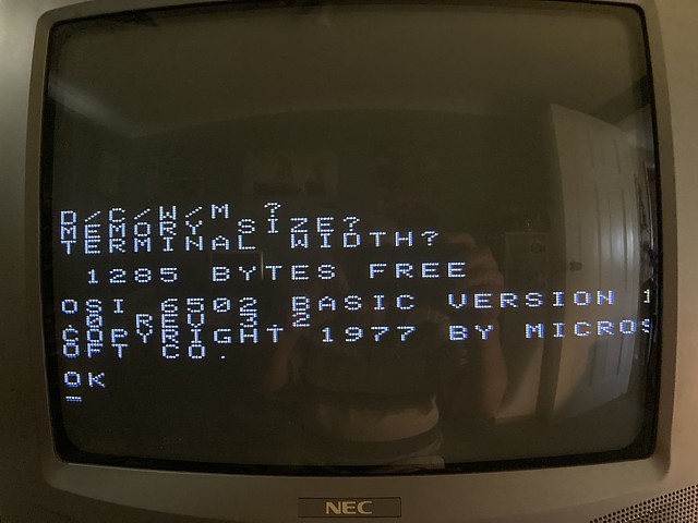
I've fitted 4k Bytes of RAM and the message should read '3327 Bytes Free' but I'm only seeing 1285. The OSI RAM test appears to just check each byte of RAM in sequence, stopping when it does not detect a correct result. So the first 2k of RAM should be working but there is an issue in the third pair of 2114 RAM ICs.
The main RAM can be added or removed in 1k Byte increments, each pair of 1k x 4bit ICs being 1k Byte. Only the first 1k is required to boot but after the reserved memory only 255 bytes of free RAM will remain. A second pair of ICs will increase that by 1024 Bytes to 1279 and a third pair will result in 2303. Swapping the 3rd and 4th pair on this board gives me 2309 so the fault is now in the 4th and final pair.
I only have a couple of spare 2114 ICs left so substituting one at a time, for the ICs in the 4th row identifies the faulty IC and fixes the problem. I now have the correct '3327 Bytes Free' message showing on screen.
So it's time to check the basic operation with some meaningless program, finding the unmarked keys is a bit tricky so we'll keep it brief:
10FORI=1TO24
20?"HELLO WORLD"
30NEXT
Old habits quickly resurface and it seems as if I'm transported back to 1980 - omitting spaces as they waste valuable RAM - did I mention this computer has less than 4k free to work with?
That runs as expected so now having a short program in memory the next step is to test the all important cassette interface. I don't have any pre recorded program tapes to load, my old tapes and hand written programs sadly having gone with my original computer years ago so I will begin by saving the current test program to a blank tape.
I have a suitably old mono cassette recorder to use with the Superboard, which I picked up from a pile of junk left out for kerbside collection. With a clean and a new drive belt it seems to play OK but to begin with I'll use a higher quality Onkyo cassette deck which has manual level control, metering and monitor output to ensure an optimal recording.
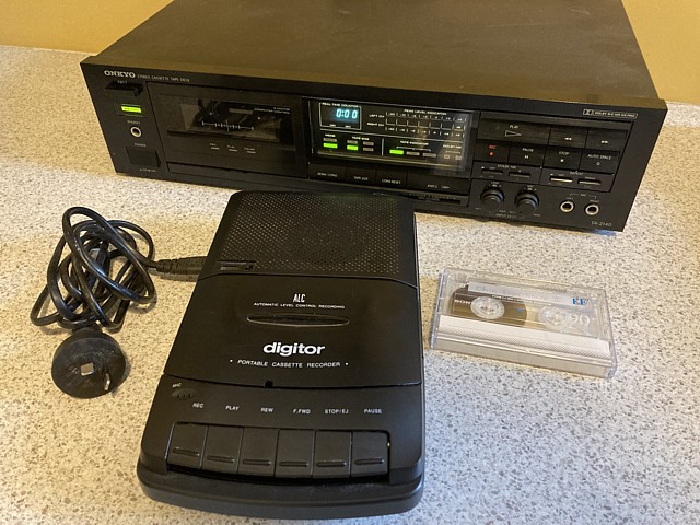
The cassette is the only one I had which was still wrapped and unused, I've since used it to save a couple of Commodore 64 programs to tape so for the Ohio I'll turn it around to side B and rewind the tape to start with an unrecorded and unworn section. The Onkyo cassette deck is stereo of course so I'll just record the program onto the left channel and leave the right channel blank.
Using the SAVE command then LIST and starting the recording before pressing return, the program seems to record well and sounds fine on the headphone monitor. Now using the BREAK key to reset the computer, after startup prompts typing LOAD and replaying the tape - nothing happens.
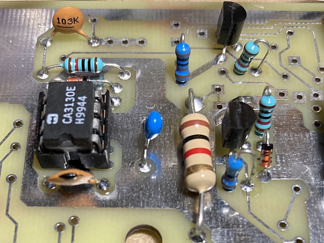
If there was an issue with the recording having marginal level or noise I would expect to see some random characters appear during the LOAD operation so I'm guessing there is some hardware problem either with the 6850 or the input circuit around the CA3130 comparator IC.
I have my oscilloscope handy so will begin with the signal arriving at the comparator. At this point there is a pair of diodes back to back to square up the signal and limit its amplitude so there does seem to be sufficient input level for that to occur. There is however no signal on the output pin 6 of the CA3130 comparator IC.
That part could well be faulty or may even have incorrect markings - at the time I was ordering parts for this project my usual suppliers had no stock of this item so I ordered a small quantity from an overseas seller online. Testing each of those yields the same result so I'll try to find some locally available stock to replace this component.
- With a bit of searching I have managed to find some local stocks of this item so, picking up where we left off the LOAD operation now works perfectly and the program which I saved earlier now loads, lists and runs without error.
Next trying a SAVE and LOAD operation with the Digitor cassette recorder, unfortunately does not work and reveals an issue with its recording levels. There appears to be a problem with the input amplifier or possibly a lack of bias to the record head so the playback level is too faint to be useable. No matter, I'll put that aside for the moment and should be able to repair it at a later date.
Moving on to the faint composite video image on my TV monitor, I believe that issue is more to do with the TV not being suited to the Superboard's video standard. The TV is a PAL standard, colour model which can display the 60Hz monochrome signal but its composite video channel would have a filter to suppress the chroma signals which centre around 4.43 MHz for PAL as opposed to 3.58MHz for NTSC.
The Superboard's dot clock frequency being 3.93 MHz may be a bit too close to the PAL chroma frequency, causing a reduced response - in any case a black and white TV or monitor would be more suitable but I unfortunately don't have one to try.
The next best thing would be to use the NEC TV in RGB mode with separate sync, this will give a better response having no chroma filter in the video channel and I can just use the green input which will give a clearer display than white text on the colour screen, with no convergence issues.
Getting separate video and sync from the Superboard is quite simple as these signals are just combined at the final output stage to provide the standard composite video. Looking at the connector J2, pins 7 to 12 are used for the cassette I/O and composite video output but pins 1 to 6 are not used, only connecting to a part of the PCB which is not populated.
It appears those pins were reserved for additional serial data and clock signals, maybe for synchronous communication but as they are not implemented in the standard configuration I'll use pins 4, 5, and 6 for Video, Sync and Ground.
Adding a ground point is simple, linking pin 6 to 8 and sync (pin 5) is just linked directly to pin 12 (composite video) then the video level reduced by turning R58 anti clockwise. Finally the video signal from IC70, pin 6 is linked to J2, pin 4.
And here is the result, a nice looking 'green screen' - even though it is really just a colour TV monitor. I'll keep an eye out for a dedicated Black and White monitor or TV to use with the Superboard but meanwhile this will do just fine.
The Ohio Scientific Superboard II reproduction appears to be fully functional with the video monitor now showing a clear image but there's one little extra which I'd like to get working with this computer. My original Superboard had no means of producing a hard copy program listing, only being able to save or load programs to and from audio cassette.
I'm pretty sure that computer was a Rev. B whereas the Klyball reproduction is of the Rev. D PCB. The Superboard had provision for an RS232 interface which was not populated on the Rev. B but the required components are fitted in the Rev. D version. A 12 way Molex 'shorting plug' configures the single serial port for either cassette, RS232 printer or modem / terminal connection.
Apparently the Challenger model had a rear panel mounted 3 position rotary switch to select the serial destination. I'd like the ability to select between the cassette and printer interface so that a program can be loaded, edited and the program listing printed out before saving again, without the need to remove and swap plugs. This can be achieved with the addition of a 3 pole, 2way toggle switch.
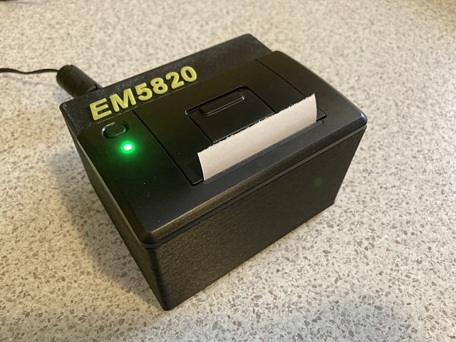
Now all we need is a compact printer with an RS232 interface, capable of printing ASCII text and at least 24 characters per line - and this is what I've found:
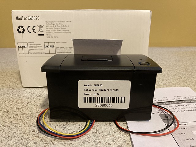
OK, so it's really just intended as a receipt printer but why not use it with the Superboard? It is very compact, has RS232 interface and its default font will print more than 24 characters per line so should be fine for program listings. It requires no ink and uses standard cash register style thermal paper rolls. The only immediate issue is its 9600 Baud rate default.
The Superboard does have Baud rate selectable via a link on connector J2 but the two default choices are 300 Baud for the cassette or modem and 1200 Baud for RS232 printer. Fortunately by utilising the undivided clock frequency CLK signal the highest available, 9600 Baud rate can be obtained. Thanks to Mark Csele for mentioning that in his technical description of the Superboard II (link below).
To make the Baud rate switchable between 300 (for cassette) and 9600 (printer) I need to link the CLK signal to J2. Pin 11 is listed as unused but is actually connected to +5V so I'm cutting the track from pin 11 just near the point where it joins the +5V rail, instead adding a link to the CLK signal at the nearest point, U59 pin 2.
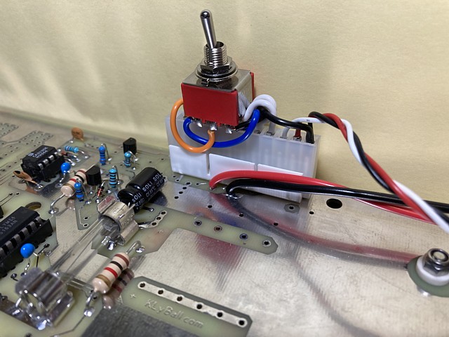
Here's the J2 socket with 3 pole toggle switch to select cassette or printer operation. I'm not planning to put this new Superboard into a case, just keeping it as a standalone PCB this time so I've wired the switch directly to the socket pins rather than extending the wires to suit panel mounting. At this stage I don't envisage using the Superboard with a serial terminal but could make up a separate socket and just swap them over to change the configuration if required.
That reminds me; the first 'printer' I ever bought in about 1984 was a second hand Digital LA30 DECWriter in working condition, complete with full keyboard and stand (see link below). I wish I'd had the space to keep all of the historic equipment I picked up over the years, those were the days when real computers and peripherals required floor space rather than desk space.
Meanwhile at the other end of the scale it's time to test the little thermal printer with the Superboard, powering it up with a 5V, 2A supply and connecting the RS232 printer port. Once the SAVE command is entered all of the output from the Superboard is duplicated to the serial port including commands typed, program listings and print statements. To discontinue printing the LOAD command is entered followed by space and enter keys.
So, typing in SAVE followed by LIST and RUN commands, the little printer buzzes away and here is the result:
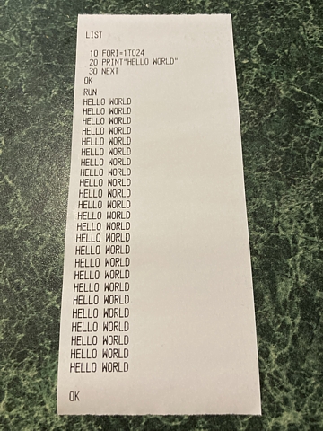
Terrific! I would have loved to have had a little printer for my original Superboard back in the day, to print out listings of programs I had written rather than copying them out by hand. The irony here is this modern receipt printer probably has way more embedded processing power than the computer which now controls it.
The narrow printout is very reminiscent of the ones produced by the original school computer printer except that one printed onto metallised rather than thermal paper in a process known as 'spark printing'.
So having proven the concept I'll fit the thermal printer module into a case of some sort - it is designed to be panel mounted inside some larger equipment, cash register etc. Originally I planned to use a standard 'Jiffy' type enclosure, cutting openings for the printer top panel, power and interface connectors but none of the readily available housings were a good size match so instead I decided to design and 3D print a custom enclosure to suit the exact dimensions of this device.
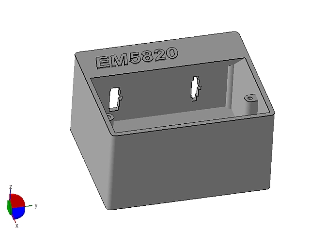
Here's the design for a simple enclosure made in one piece which the printer module can drop into, with a little extra space at the rear for connections. I've chosen a Molex style 2 pin connector for 5V power and a 3 pin Mini Molex type for the RS-232 interface, aligning the rear panel cutouts vertically to minimise their unsupported overhangs. I've also added a tapered support for the top surface so the part can be printed with no additional supports and minimal infill.
And here's the finished product, printed in ABS. The cutouts for the connectors printed almost perfectly, I had made them a snug fit so just used a small file to finish them off. The connectors themselves are readily available from Jaycar, Part Numbers PP2020 and PP2023. Each comes as a complete set so there is no need to buy pins or mating connectors separately.
One little trap I've noticed; if the interface is set for printer operation but the printer is not connected and ready the screen will not update as the computer waits for a /Clear To Send signal. This appears to be normal behaviour and not a fault so the best practice seems to be to leave the interface set for cassette operation unless actually using the printer.
So, with the reproduction Superboard II now working and the RS-232 printer complete and tested all that remains is to source a set of key caps and to repair the portable cassette recorder which I had planned to use for program storage, when time permits.
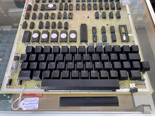
My Ohio Superboard II (reproduction) is tested and working now, only requiring a set of key caps to be complete and fully functional. I believe original style key sets for the Superboard have been reproduced in small batches and some may still be available. While this would be the ideal choice I suspect the cost with shipping from U.S. - worsened by our poor exchange rate and import taxes would exceed my budget at the moment.
For now I'll make do with a generic key cap set. There are more than enough caps in the set and the alpha numeric keys will be fine but some of the symbols and functional keys will not match the original markings. I'll have to look into replacing or re-labelling those at some point but the main problem with the generic key set is the width of the space bar.
The Ohio keyboard layout resembles a traditional typewriter with a large spacebar centered below the bottom row of letter keys while a modern style computer layout adds several functional keys to that row e.g. Ctrl, Alt, Windows / menu keys and uses a shortened space bar to fit all of the additinal keys within the bottom row.
The space bar used on the superboard has a width of 8U, with 1U being the size of a single letter or number key. For the Cherry key switches and caps that is a 3/4" square (about 19mm). The actual key cap dimensions are just a little smaller at about 18mm, presumably to include some clearance between adjacent keys.
The most common spacebar width, as included with the generic keycap set is only 6.25U. Like most people I'm used to a modern PC keyboard so wouldn't mind using the shorter bar - but the problem is that does not fit the 8U stabiliser which fits the reproduction Superboard PCB.
The stabiliser works much like an anti sway bar on a car suspension, keeping the wider key cap level when pressed off centre. Without it the space bar would behave more like a see-saw and apart from not operating reliably something would soon break. Stabilisers are available to suit key widths from about 2U to 8U and the Superboard II reproduction PCB incorporates the mounting centres for an 8U stabiliser to suit the original style 8U space bar.
So the options would be to modify the PCB to fit a narrower stabiliser for the 6.25U space bar - messy and difficult - or to source a Cherry MX style 8U space bar. How hard could that be? As it turns out, seemingly impossible. Despite a huge range of aftermarket key sets and individual key caps being available, mainly to satisfy the demand for custom gaming PC keyboard layouts I couldn't find any readily available 8U space bar online.
As with any simple plastic part which seems unobtainable the obvious solution is to 3D print a substitute and being a technical challenge of sorts I will attempt to do exactly that.
Beginning with a few test prints we can see the evolution through to final product in the picture below. On the top row a couple of tests to try and reproduce the 'standard' actuating post for the Cherry key switch using my filament type printer and ABS material. It seems my printer lacks the resolution to match the fine detail of an original moulded key (bottom row of picture)
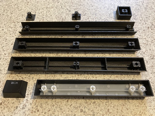
Looking for a more print friendly option, I mock up a single key with rectangular post to exactly match the actuator shape within the Cherry key switch (top right of photo). That does work but is prone to jamming with insufficient clearance around the post when the key is pressed down. The square key with no taper and 1mm wall thickness already looks and feels too heavy compared to an original moulded key cap.
In the next row of the photo. I've mocked up an 8U (6") long bar with 3 round posts correctly spaced. 3mm taper front and back and wall thickness reduced to 0.8mm looks better than the previous 1mm. I've added a stiffening web to the top span which has also been reduced to 0.8mm thickness but the round posts are still impossible to accurately reproduce using my filament type 3D printer.
Next we have the first functioning prototype. I've added tapered ends with 3mm taper to the ends and front, reducing the taper at the rear to 1mm also adding a slight chamfer to the top edges and I've switched to the rectangular posts. This version looks good and fits well apart from the centre post which is still tending to jam inside the body of the key switch when pressed dowm. The unsupported front and back faces prove too fragile and crack between laminations when flexed.
In the final version I've reduced the outer dimensions of the centre post to prevent jamming, increasing the dimensions of the other two posts to add strength and rigidity where clearance is not an issue. I've also added some bracing for the front and back faces to reduce flexing. The difference in width between the final 8U space bar and common 6.25U bar can be easily seen in the bottom rows of photo above.
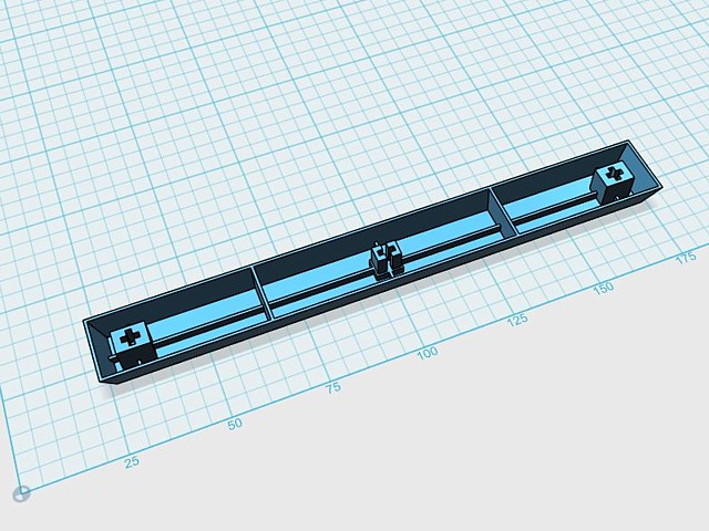
Here is the final design for the 8U space bar and below, 3D printed unit fitted to the Superboard II along with the generic keycap set. The metal stabiliser bar and mounts can just be seen in the photo beneath the space bar itself and the generic 6.25U space bar included in photo once again for comparison.
That done, the Superboard II reproduction is now a going concern. I may look to relabel the existing key caps or replace the entire set at a later date. Meanwhile I'll try to brush up on my BASIC programming skills and see if I can recollect some of my earliest experiences and fondest memories of my original Superboard II, all the way back to 1980.
Now that my Ohio Superboard II reproduction is complete and running I'd like to set it up somewhere and run some programs on it - maybe even try to rewrite some of my old BASIC programs, the original tapes and listings having been lost to time.
As yet I haven't found a black and white CRT TV or monitor to use with the Superboard and dedicating a colour CRT TV to the very low resolution monochrome graphics seems like a waste so in the interim I'll try a 4:3 (non widescreenn) LCD TV monitor which I have to spare.
I had already tried a small 7 inch in-car style LCD monitor with the composite video signal from the Superboard but it continuously dropped in and out of sync. I put that down to the non standard timing of the video signal, having only 256 lines per 60 Hz frame compared to about 262 for NTSC.
That alone could be enough to stump a lot of LCD monitors, not to mention that TV video signals are interlaced, alternate 60Hz fields beginning or ending on a 1/2 line while the Superboard II and most computer video outputs of the era are non interlaced.
Having said that, this particular 19 inch LCD TV monitor seems to cope with the non standard timing but I'm experiencing issues with poor contrast and marginal sync due to the composite video output levels from the Superboard II. That is similar to my previous observation using the composite video input of my colour CRT monitor.
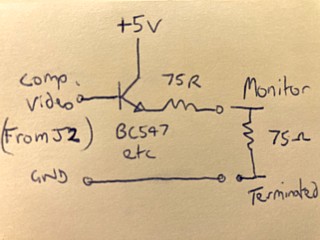
Taking some measurements around the video and sync output section I'm guessing that the composite video output was designed around black and white monitors or video converted televisions with relatively high impedance inputs and not terminated with 75 Ohms.
A lot of monitors at the time had loop through inputs and used separate terminating plugs or switchable 75 Ohm terminations while most modern video monitors, apart from professional or broadcast models, have permanent 75 Ohm terminations on their composite inputs.
On the Superboard II, video and sync signals are driven by TTL gates with open collector outputs and pullup resistors combined by potentiometer R58.
With no external load the proportion of video and sync can be adjusted well however placing a 75 Ohm load across the composite video output affects the level and balance of video and sync.
In fact when R58 is turned fully clockwise the video level at the output pin 6 of IC70 actually decreases under the additional load.
Rather than attempting to modify the monitor in question I decided to try adding a simple buffer to drive the external load without loading the composite video output from the Superboard II.
I've included a 75 Ohm output resistor to improve the matching between source and load as well as reducing the composite video to a more standard level, the unloaded output having over 2 Volts of signal.
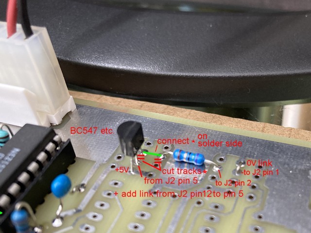
The buffer could be inserted between the output side of R58 and pin 12 of J2 but I've left that connection intact and added it to an otherwise unused section on the PCB, relocating the composite video cable to J2 pins 1 and 2.
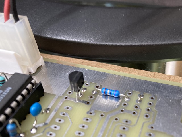
On the Rev. D PCB U67, U68 and associated components are not populated and J2 pins 1 to 6 unused so the existing traces can be utilised as shown here.
When tested with the composite video inputs on both my colour CRT and LCD monitor the contrast seems to be greatly improved. It also appears to have solved a marginal sync issue with the LCD monitor as pictured here.
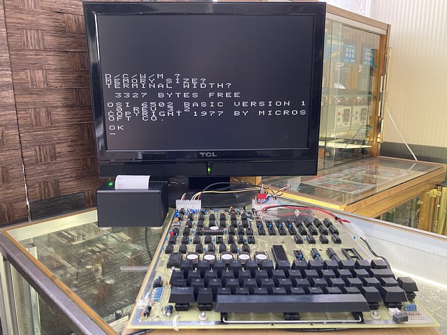
Although the original Superboard II composite video output would be perfectly fine for use with black and white CRT monitors of the era the signal isn't well suited to the standard 1V, 75 Ohm terminated inputs of colour CRT or LCD video monitors. Adding a buffer and source resistance seems to improve the image quality with some modern monitors however some LCD displays may still be unable to sync to the non-standard signal timing.
My Ohio Superboard II computer (reproduction) is set up and working, with an LCD monitor at present however I've recently picked up a portable black and white (CRT) TV which just needs a tidy up and composite video input conversion to work as a monitor.
I also have an old style mono cassette recorder which I plan to use with the computer for program storage and loading but it needs a bit of an overhaul as its record level is way too low so I will see if I can get that working soon.
Meanwhile I'd like to try the computer with some of the proprietary software which was available for the Superboard II / Challenger 1 computers. And what better example than 'OSI Invaders' which appears to have been issued for the C1P system at the time.
I recall the original Superboard II computer which I bought in 1980 came with a couple of program sample tapes but not this particular program, That's probably because 'OSI Invaders' appears to require 8k Bytes of RAM memory on board while my entry level Superboard II computer was only populated with 4k Bytes of RAM.
Similarly, I'd only installed 4k Bytes of Static RAM (8 x 2114, 1k x 4bit ICs) into my reproduction PCB initially but to get the most from my new system I've now added the remaining 8 ICs to the empty sockets bringing my system RAM to a 'full' 8k Bytes.
A number of original programs for OSI systems can be found via links on the osiweb.org site. As my system has no disk interface I'm interested in software which was originally issued on tape. These programs can usually be downloaded in .tape format to run on one of the OSI emulators or .wav (audio) format to load into an actual system via the cassette interface.
The .wav files can be played out of computer and recorded to cassette (that will have to wait until my cassette recorder is working properly) or just played directly into the cassette input of the Superboard II as it loads the program.
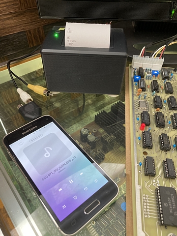
In this case I have copied the .wav file directly to an older model phone (with headphone socket) turned the volume up and loaded it from there without any issues.

According to some notes, the procedure was to begin with a cold start pressing 'C' ENTER ENTER then BREAK and 'M" then "L' to commence loading. After a few minutes loading the machine program and data followed by BASIC, the program ran upon completion.

Not a bad adaptation of the game considering the limited hardware resources and lack of sound. It has no trouble with speed of play and gives a choice from impossibly fast on level 1 to very slow on level 15. I started it on level 9 which seemed quite playable.

- More updates on the Superboard II and its peripherals to follow soon.
Ohio Superboard II model OSI600 (original) specifications
| Made | From 1978 |
| CPU | MOS Technology 6502 @ 0.98304 MHz |
| RAM | 4 kByte expandable to 8 kByte, plus 1 kByte video RAM |
| FDD | Required 610 Expansion board |
| Ports | Cassette / Serial, Expansion (40 pin DIP socket) |
| O/S | OSI 6502 BASIC V1.0 |
| Display | Monochrome, 24 x 24 characters displayed |
| Sound | None apart from 8 bit DAC which can be used to generate sounds |
| Monitor | Monochrome Composite Video |
| Keyboard | On board, 53 keys |
| Speakers | Not included but amplified speaker can be connected to DAC output |
Web Resources (External Links) -
Dave's OSI Repository - osiweb.org
KLyBall's Vintage Computers - klyball.com
Mark's Ohio Scientific/Compukit UK101 Archive
Ohio Scientific Superboard II - Mark Csele
Ohio Scientific Superboard II Replica - Jeff Tranter, YouTube
DEC and Centronics Introduce the First Dot Matrix Printers - History of Information
All images and text on this website are Copyright.
Contact: jbtech at telstra dot com