RGB Modded Sanyo TV
Caution, CRT TV's and monitors have dangerous voltages, even when switched off. Please don't take any risks and don't work on them at all if you are not familiar. Always safely discharge the High Tension from the CRT before performing any work. Many older TV's and monitors have a 'Live Chassis' and must be used with an isolation and / or stepdown transformer and not connected directly to the mains.
Updated 2/6/20
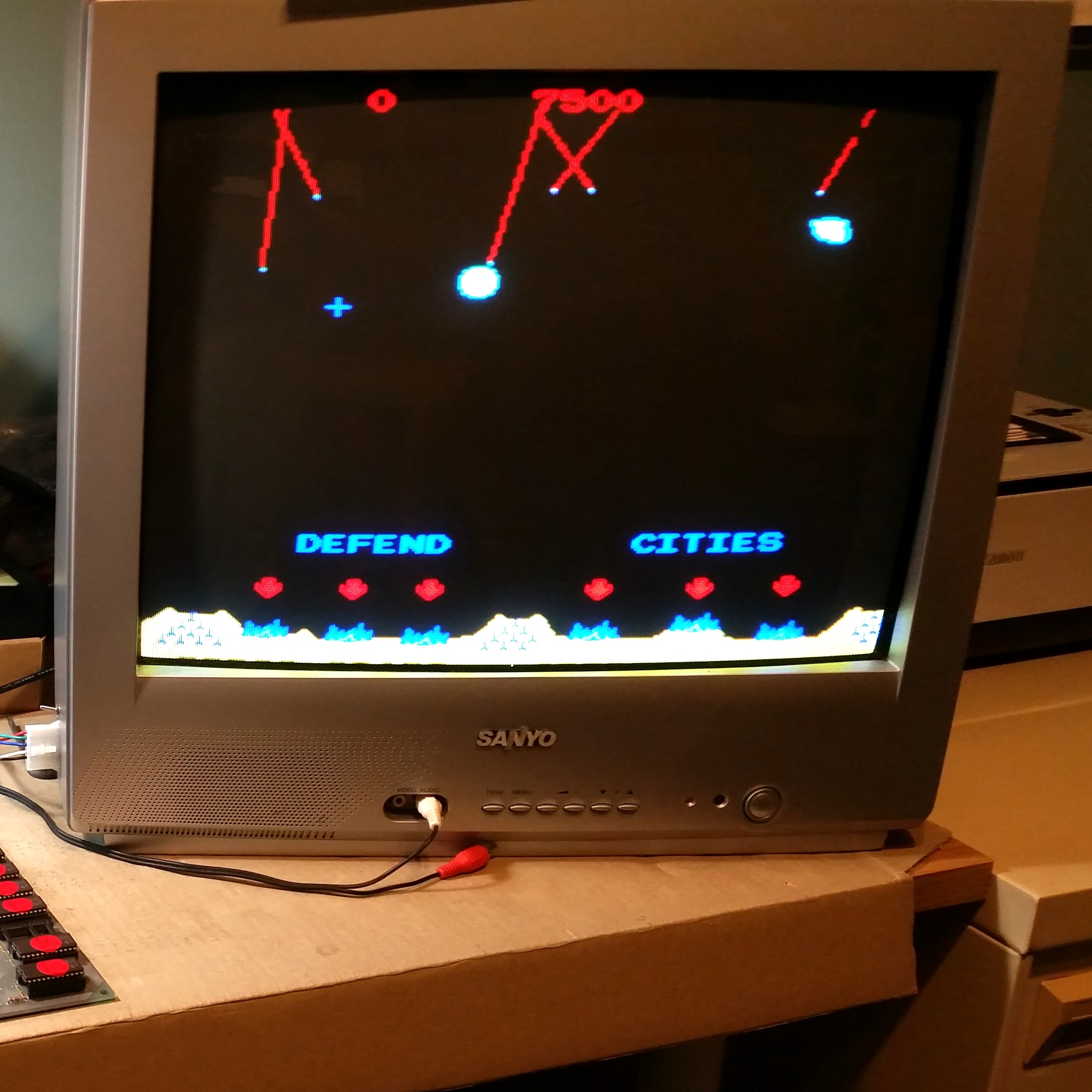
I picked up this working Sanyo TV for free and was mainly interested in its 51cm CRT as a possible spare for one of the arcade machines. In the short term however what I really needed was a standard resolution RGB monitor for the workbench, to test some Arcade PCBs.
Not many TVs sold in Australia have an RGB input as standard, Those that do are usually recognizable by a SCART type connector on the back. Some have provision internally, or use RGB signals for on screen display or teletext and can be modified.
This particular TV had provision for a teletext decoder which was not fitted so there is a position near the edge of the PCB where external RGB signals could be connected. The Red, Green, Blue signals and ground go to the relevant holes where the plug for the Teletext Decoder would have been. A 75 Ohm resistor to ground is added to terminate each input. This does attenuate the internally generated on screen text but for the intended purpose it isn't really a problem - if it was also still being used as a TV there are (slightly more complicated) other ways to implement the modification.

The orange and brown wires seen here go to a switch, the 'key' signal which would usually insert the teletext over the background image is used to switch the entire display between Composite (AV) input and RGB. The Sync signal is wired to the rear panel Video input socket and synchronises the display in the normal manner.
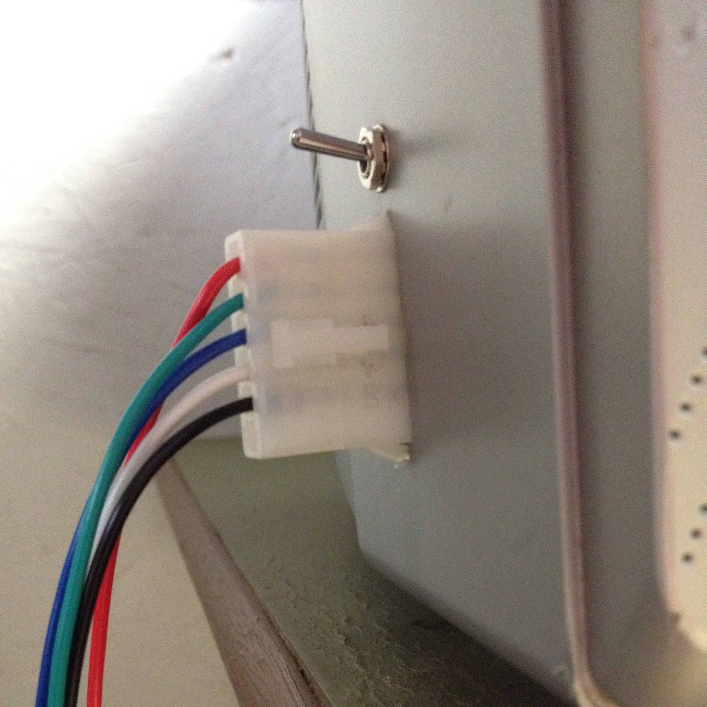
For workshop use the mini-Molex type connector, mounted near the front is more practical than a SCART or other consumer grade socket. Each test lead needs to be made up with the same, mating connector. It also makes sense - and saves wire - to have it in this easily accessible position.
If the Arcade PCB does not have an on-board audio amplifier (e.g. Missile Command) the low level audio signal can be wired to an RCA plug and connected to the TVs front panel audio input, as seen in the top photo.
All images and text on this website are Copyright.
Contact: jbtech at telstra dot com