Space Fever (Colour) PCB repair
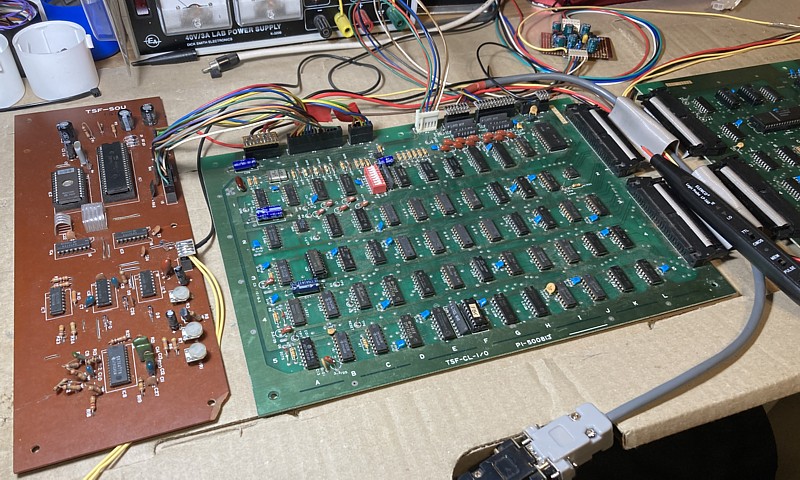
I have another Nintendo Space Fever PCB set for repair, this one is the Colour version. Setting it up on the bench for testing is straightforward - I can use my existing Space Fever test leads along with the colour video cabling and analog inverting amplifier which I recently made to repair a Space Firebird PCB set.
On first power up there is no sign of activity whatsoever. Checking the Voltages +5V, +12V and -5V as well as ground all are making it to the PCBs. Next looking at the signals around the 8080 CPU, one of the two clock signals is missing. The 8080A requires a clock signal of around 2 MHz with two phases, each having an amplitude of 12V whereas all other signals to and from the CPU should match standard 5V TTL levels.
Checking the circuit diagram, the two clock signals originate on the I/O PCB and are driven by a 75361 IC in position 2B which provides the 12V signals. This in turn is driven by a 74LS164 shift register in position 1B which provides the 2.016MHz signal, being a 1/10th division of the original 20.160MHz clock frequency.
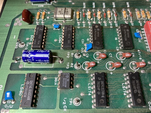
The second phase is created using a J /K flip flop, 74109 in position 3B and when checked this component appeared to have correct signals at its inputs but no output. I don't have any spares of the 74109 but the 74LS version is still available and should work equally well in this situation.
After a short wait the new 74LS109 ICs arrived by post. Having removed the faulty component and installed a socket, now fitting the replacement and powering on we get this:
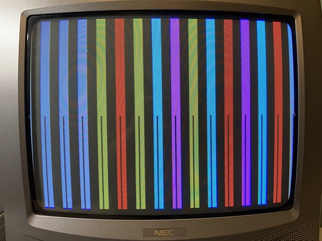
That represents some progress at least but this type of pattern is typical of a CPU program which fails to run for some reason. Going back and checking signals around the CPU, both phases of the clock signal are now present. The reset input goes high briefly upon power up then returns to a low state which is correct for the 8080. There does not appear to be any sort of watchdog timer on board so the CPU is not being reset repeatedly.
The CPU appears to be running, the address lines are all active with levels looking correct but they seem to have a fairly repetitive appearance as if the program begins to run but gets stuck in a loop for some reason. This could be due to incorrect data from the program EPROMs, some problem with their addressing, RAM errors or many other possible causes if none of the above.
Looking at the data lines of the CPU now the picture is not so pretty, all are active but there is quite a bit of low level junk on the waveforms which looks wrong. It could be these low level patterns are occurring during inactive periods between CPU read or write operations, when the data lines are in a high impedance state but could also be caused by a bus conflict for example if two devices are selected to output data onto the bus at the same time.
I'm working on a Space Fever Colour PCB set by Nintendo and have corrected a missing CPU clock signal but the program is not running properly, just outputting stationary bars of colour on the screen. I've checked the outgoing address lines from the CPU before and after their 74LS08 buffer ICs, these look fairly normal with correct levels.
Looking at the data lines however I'm suspicious of some low level signals which may be occurring during the bus 'idle time' or may be corrupting the data received by the CPU and as a result affecting the program flow.
Checking the circuit diagram, to me the data bus structure seems surprisingly complex for such a straightforward game. The data pins of the 8080 are bi-directional but the two 8216 type buffers which connect those to the rest of the circuit divide the signals into separate paths for incoming and outgoing data. The switchover is controlled by the CPUs DBIN control signal via an inverter, when checked this appears to be toggling as expected.
The incoming data arrives via a set of 74LS153 multiplexers which select one of four possible data sources; ROM, RAM, Input and Interrupt. In a more conventional configuration data would arrive via a common bus and individual data sources would be selected onto the bus one at a time by address decoding.
Just to ensure that I'm not chasing a false lead I'll begin by replacing the pair of 8216 buffers which transfer data between the CPU and multiplexers. It turns out this doesn't solve the problem and makes no change to the glitches on the data signals but at least I have eliminated this first stage from suspicion so it is a small step in the right direction.
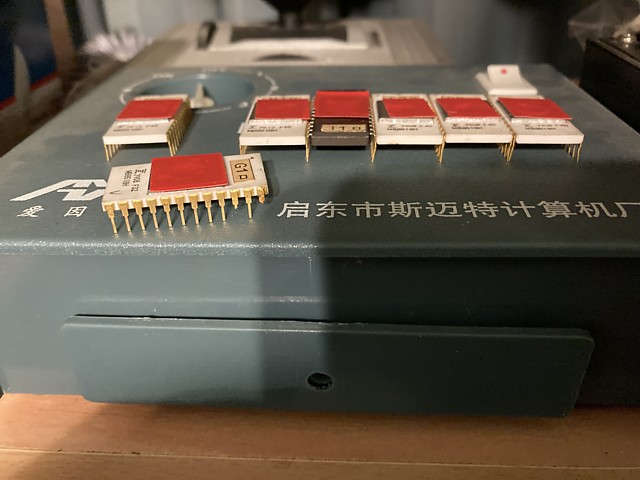
Concentrating on the ROM and RAM data now, the data returning from the EPROMs looks quite glitchy so I'll begin there. The PCB has a bank of eight sockets for ROM addressed from 0 to 8k, the first seven are populated with MB8518 ceramic package ICs compatible with 2708 EPROMs, each 1k x 8 bit (or 1kByte).
There are two concerns with these ICs, the first being they require 3 supply rails to operate (+5, +12 and -5V) compared to more modern types which only require +5V. I have one EPROM programmer which should be able to read them and reprogram as required, if I make an adaptor to fit between the EPROM and programmer which supplies the extra Voltage rails. I would pursue this option only if necessary.
The second issue and potentially most serious is these ceramic package ICs with gold pins are notoriously fragile. The pins themselves I believe are steel and protected by gold plating but incredibly thin and after more than 40 years of use and / or storage in variable conditions some moisture tends to penetrate and corrode the pins making them very weak and brittle.
I would normally try and diagnose the circuit around them and avoid removing them if possible but in this case we plan to change the program so this PCB will be able to run the 'High Splitter' version of Space Fever so the originals need to come out sooner or later anyway.
Carefully prising them out with a flat screwdriver, a little at a time I manage to remove all but one intact. The IC from position G1 suffered two broken pins. On close inspection the stubs of the pins have some brown marks on them suggesting a bit of rust had already set in. The broken portion of the legs remained in the socket so that will need replacement to begin with.
It's easy enough to solder on some 'new' IC legs cut from a faulty, donor IC so that EPROM could still be read and possibly reprogrammed. The most straightforward way to convert this PCB to run the High Splitter version software would be to erase and reprogram the existing EPROMS. One additional 2708 or equivalent IC would be required as the High Splitter version requires eight 1k EPROMS for the CPU PCB whereas the original Space Fever ROMset only uses seven.
A more interesting approach in my opinion would be to replace the EPROMS with eight 2716, 2k x 8bit ICs. This would allow both the original and High Splitter versions to be contained within and simply switched so that either software set could be run without having to remove and replace the EPROMs. Some minor PCB modification would be required to configure the existing sockets to the correct pinout for the 2716, fortunately only 2 pins would need to be changed.
The third option which is the quickest and easiest solution and the one which I will implement just to get the boards up and running is to use a single 27128 EPROM which will contain both entire ROMsets, making the extra connections with some fine wire-wrap style wire. The advantage of this configuration is no PCB tracks need to be altered or cut so the modification is completely reversible and can be returned to original or modified to a bank of 2716 EPROMs at a later date.
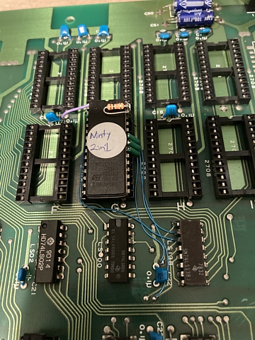
The 27128 EPROM has a capacity of 16k x 8 bit compared to the original 1k x 8 bit 2708s so has four additional address lines A10, A11, A12 and A13. These signals all appear as inputs to the original address decoder 74LS138 in position 3H.
A13, which is used as a select line for the entire bank of 8 EPROMS in the original configuration is connected to the /OE (output enable) input of the 27128 while the EPROM's A13 input pin is used as a 'bank select', pulled high via a 10k Ohm resistor to select the original Space Fever software or held low to select the High Splitter Version.
Initial progress with the Nintendo Space Fever Colour PCB repair has been slow but steady, as the program fails to run there are many possible causes. I've already corrected one problem with a missing clock signal so there is obviously a second fault and possibly multiple issues to solve. To eliminate the original 2708 EPROMs from the equation I've substituted a single, 27128 IC programmed with the entire Space Fever and High Splitter ROMsets.
So, having swapped out the original EPROMs has there been any improvement to the fault symptoms? Well, yes and no - there does seem to be some initial flickering on screen which I don't think was there before but the program is still stalling at an early stage and not progressing beyond the 'coloured bars on screen' symptom.
For the moment I'll assume there was some EPROM issue whether it was corrupted data, corroded pins or bad sockets but the current setup appears to be functioning as expected so we'll move on to checking around the RAM area.
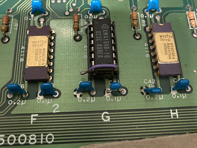
The Random Access Memory comprises 8 x 4116, 16k x 1 bit dynamic RAM ICs with supporting logic hardware. To keep their footprint to a minimum (for the time) these ICs used addresses divided into Rows and Columns, effectively halving the number of address pins but requiring a fair bit of extra support logic to multiplex the address bus from the CPU as well as Row and Column Address Strobe timing signals to control them.
The /RAS and /CAS signals are present and appear to be correct, addresses from the CPU seem to be reaching the RAM ICs correctly via the four 74LS153 multiplexers which create the row and column addressses. The data input and output pins of the RAM ICs are all active but when using a logic probe to quickly check for the presence of these signals the output from the RAM in position 5G sounds different on the logic probe's tiny inbuilt buzzer / speaker.
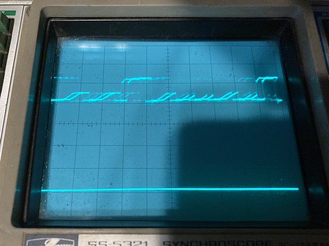
Using the oscilloscope to have a proper look, when the output signal goes low the initial negative edge appears fine but then the signal bounces back slightly and settles at about 1 Volt. This is too high and would need to be 0.8V or less to be a valid logic LOW. It's not far outside of specified limits but the logic probe has correctly responded, indicating the pulse but not the logic low state.
The problem is most likely a faulty RAM IC but could otherwise be due to an external load on the signal from the following input or a shorted PCB track. Inspecting the area around the RAM visually with a magnifier I can't see any potential shorting issues, in fact the PCB itself seems in very good condition for its age.
That leaves the possibility of another component loading the signal, in this case that could only be the 74LS08 in position 4F which buffers the output from the RAM IC in question. I'd rather replace a simple logic IC than the fairly scarce 4116 RAM so will try that first, adding a socket to that position in the process.
Unfortunately that doesn't change the situation so it looks as if the RAM itself must be at fault. To check I'll carefully desolder the 4116 in question, install a socket and try a spare IC. At least I've minimised the risk of installing a new RAM IC only to have it fail due to an excessive load on its output.
I have a couple of spare 4116 ICs left from a batch of about 5 which I bought a few years ago. Even then the 4116 had been obsolete for so long that old stocks appeared to have dried up locally and available parts were most likely recovered from old PCBs.
At the time I did manage to use a few to successfully repair my Missile Command PCB so those worked fine but when I try the remaining ones in this PCB both have no output signal at all. That's worse than the original IC so putting it back in just to double check, its output is as before.
So, both of my spare 4116 ICs appear to be duds. I'll have to try and order some more, meanwhile I have a 4164 which I previously used with a couple of minor alterations, in place of the 4116. The 4164, being 64k bit instead of 16 needs two extra address lines but as these are divided into rows and columns that only requires one pin for both. It also only needs a +5V supply and not the additional -5V and +12V like the 4116.
To substitute the 4164 as a temporary measure it's easiest to bend the two pins away from the socket which has the extra supply Voltages and link pin 8 to 9 which for the 4116 is connected to +5V. On the 4164 pin 9 is the additional address line so leaving that connected to +5 simply reduces the useable address range from 64k bit to 16 which is perfect for this application.
To install one, or a whole set of 4164 ICs permanently in place of the 4116 it would be neater to slightly modify the PCB tracks. Hopefully I will be able to obtain a few more working 4116 ICs so that won't be necessary. In my recent repair logs a common theme is that locating the source of a fault is only half of the process, finding suitable replacements or alternatives for obsolete components can be equally challenging.
The 4164 which I'm using here is definitely new old stock and not second hand as I bought some brand new about 20 years ago and still have them, in their original antistatic packing tube. With this one in place and powering on, the game now runs albeit with a number of issues but it's a good step forward and easier to trace remaining faults now that the program is running.
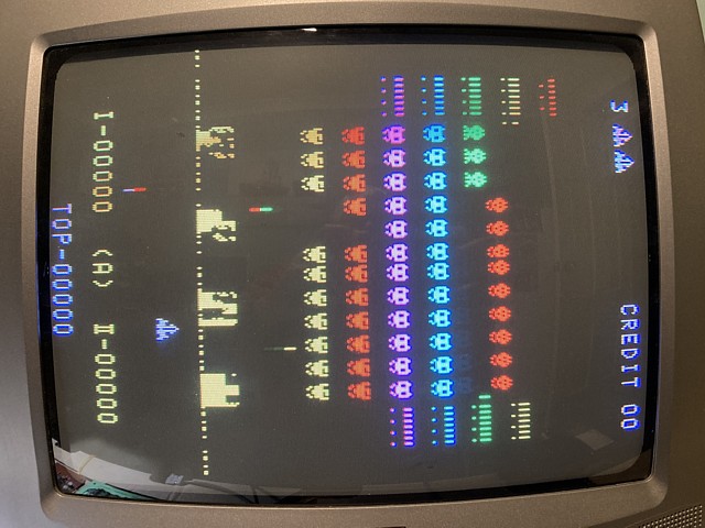
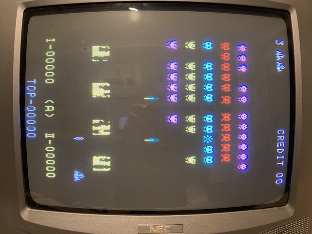
I'm continuing with repairs to the Nintendo Space Fever Colour PCB set, having swapped out a faulty 4116 RAM IC the program is now running with a few remaining issues as seen in the photo above.
There are two obvious issues and some secondary symptoms which may be resolved once the main problems are corrected. Firstly, the invaders are leaving a trail when moving across rather than a clear space. As a result, instead of moving down one row and then reversing their sideways motion they continue to move downwards until they reach the bottom and the game ends.
I also tried with the single EPROM switched over to the High Splitter version and was surprised to see the invaders marching upwards instead of down but after trying that version in MAME I realise the invaders do sometimes move upwards by a row before resuming their descent, presumably to factor in extra time to shoot the additional enemies when the large ones split in two.
The other issue which looks fairly innocuous is the dotted line which appears at the base of the barriers and is always present even during the text screens of the attract mode. I suspect this indicates another RAM error, this time one of the 4116 RAM ICs may have some bit errors in fixed locations. A faulty RAM IC such as that could cause widespread and seemingly unrelated symptoms so I think it might be wise to investigate this issue first.
To date I haven't found any ready made test ROM or home brew diagnostic program for Nintendo's Space Fever hardware. It's on my 'to do' list to try and write a simple RAM test which can be run on the CPU PCB but it hasn't been a priority thus far. In this case I should be able to trace the cause of the dotted line artifacts on screen and hopefully identify the faulty component in that manner.
Using my analog oscilloscope's delay trigger I should be able to pinpoint the moment the dots appear on screen and probe the components in the signal path to find their origin. The delay trigger is one of the most useful but under utilised features of the analog oscilloscope. A modern digital scope can also be used to acquire these signals and then zoom in on the relevant point in time - I don't have one of those so let's keep it 'old school'.
The dots we're referring to don't occur on every line but do appear at the same horizontal point on each line when they are present so we can trigger the oscilloscope on the sync signal at TP8 and adjust the timebase to 10 microseconds per division, the resulting display shows approximately two video lines with horizontal sync near the centre of screen.
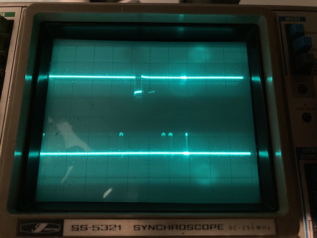
Using the second trace to display the video LUMA signal at TP9 (The black and white video prior to the colour overlay section) we can see just after the horizontal sync two blocks of characters (these are the score displays at the bottom of screen as it would be viewed from the player's perspective) then the spurious dots. This is taken when the attract mode shows only text on screen so the barriers are not present in this photo.
Switching the oscilloscope display to 'A intensified', adjusting our B timebase to 0.2 microseconds per division and adjusting our delay to highlight the moment where the dots appear, we now see a brighter trace around the area of interest. Finally switching to our B timebase, turning the brightness up a bit we can see just the part of the line which shows the 'dot' as an approx. 0.2 uSec pulse on the video signal.
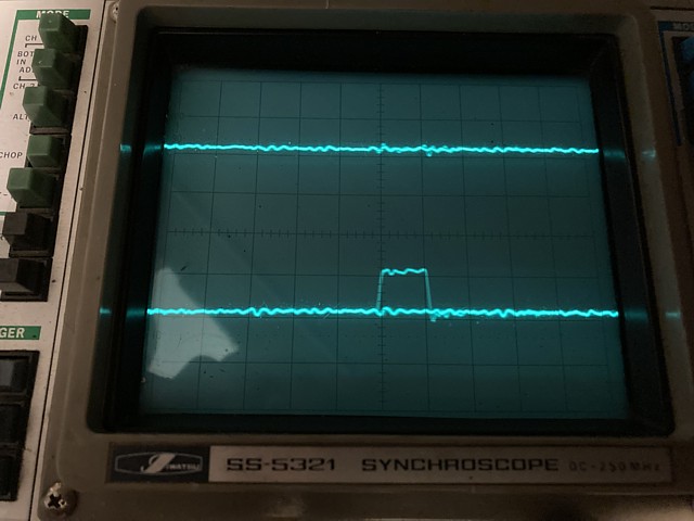
The analog oscilloscope has no storage ability so is actually displaying many lines of the video signal superimposed. Apart from the lines which contain the pulse there are also straight traces from lines where no dot is present.
Referring to the relevant part of the circuit diagram now, we can trace that signal from TP9 back via 74LS00 logic gates in positions 2K and 1K, the pulse arrives at pin 9 of 1K from the QH output of the MB455, 74198 equivalent shift register in position 1L.
Incidentally, the ICs in position 1K and 2K are both 74LS00 NAND gates and functionally identical but the eagle eyed will notice they are drawn differently on the circuit diagram. Both symbols are technically correct, the first being the shape of an AND gate but the small circle denoting an inverted, active low output. The second symbol is the shape of an OR gate but with two inverted, active low inputs.
The reason for the two different drawings is to show the significant condition which results in the desired output - in the first case both inputs must be High to result in a Low output state, in the second either input being Low will result in a High output state.
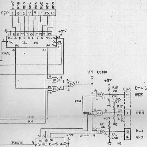
So the shift register in position 1L is loaded with a byte of data from the video area of RAM, via connector CP9 then the 8 bits are shifted out sequentially by the 5MHz approx. pixel clock signal, being 1/4 of the 20.160 MHz main clock frequency. This process repeats continuously, each byte of data containing 8 pixels of video signal. The direction of data shift can also be reversed to facilitate 2 player flip screen operation.
The control inputs of the shift register, S1 and S0 determine the function either shifting data left, right or loading the next byte from the parallel data input. Checking these signals around the time of our spurious dots it appears both are high immediately prior to the offending pulses so this would mean a new byte of data has just been loaded from the parallel input.
So the pulse on the output has not been shifted along but loaded directly from Video RAM. The corresponding input 'H' is loaded from data bit RD0 which originates from the 4116 RAM memory IC in position 5D on the CPU board.
The proof of this theory will be to desolder the RAM from position 5D, install a socket and a 'new' 4116 IC and see if the dotted line has disappeared. My small order for replacement ICs has just arrived so lets put the theory to the test...
Success! Not only has the dotted line disappeared from the bottom of the barriers but the invaders are no longer leaving trails behind as they move across the screen. As a result of that their rate of descent has also returned to normal.
After a quick test of control inputs, all appear to be working so next stop is to work on the missing sounds. At present only the invader hit and laser base explosion sounds are working at all, these sound a bit muffled while the remaining sounds and musical tunes are entirely missing.
I have the Space Fever Colour PCB set running now with graphics and game controls all functioning so it's time to tackle the sound issues. Along with the original sound PCB from this set there is a spare, at first glance it appears to be in poorer condition and very dirty but we'll start by giving them both a clean then see where we stand.
These genuine Nintendo sound boards use a single sided PCB layout so the top face has no green solder mask but the brown circuit board does have a white text overlay. The bottom has a green solder mask and both boards appear to have been sprayed with a thick coat of protective lacquer, either after assembly or during later repairs. To properly check their condition I need to clean this off, just using some alcohol and a toothbrush which gradually dissolves it away.
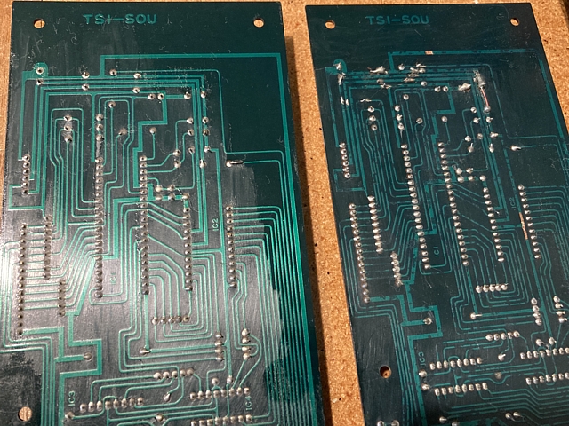
After this initial cleanup it becomes obvious that the second PCB, seen on the left in this photo is in better condition than the first. Its traces look much better than the others which are visibly tarnished under the solder mask, an early indication of 'track rot' setting in. That board also has some messy repairs and solder blobs near the top of photo which need to be checked and tidied up.
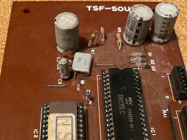
On the component side the situation is the opposite. The board which has the better looking PCB and tracks shows more tarnishing and corrosion of its components while the PCB with the poorer tracks seems to be in better condition above. It would be possible to swap all the better looking components across to the better PCB but these boards are too valuable to just use one as a donor to fix the other. As always I'll attempt to repair both PCBs if possible.
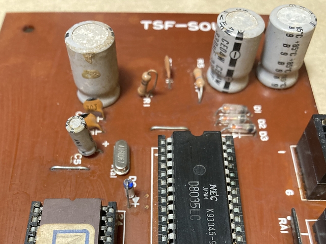
A quick test of the 'spare' PCB with the poorer looking components produces no sounds from its output. Checking the Voltages and signals at its 8035 Microcontroller IC reveals no clock signal, sure enough the 6MHz crystal has some corrosion around its base and one of its pins has broken off. I don't have a spare one so will add that to my next parts order and put the PCB aside until the replacement arrives.
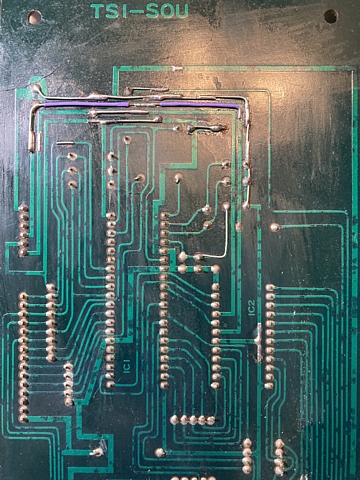
Getting back to the first sound board and checking the area around those previous repairs, there is a fine crack in the board which had broken a number of tracks. These had been bridged with blobs of solder and a piece of wire in one section which may have worked but could definitely use a tidy up. The tracks in question carry the Voltage rails and ground via some filter capacitors to the rest of the circuit so an effective connection is important.
I've removed the messy solder bridges and added some wire to span the broken tracks also replacing the electrolytic capacitors in this section. The track repairs are pretty obvious but they are on the underside of the PCB at least and should ensure a reliable connection for the power supply rails. From the general condition of the PCB it's likely other tracks will need to be repaired at some point, finer tracks can be bypassed with some kynar coated wire-wrap style wire where necessary.
Double checking the component side of the PCB I've noticed a couple of resistors next to the SN76477 complex sound generator IC which had been pushed over and one leg broken on each. This may account for the slightly off sounds which I did hear on initial test so, after replacing those the next step is to re test and diagnose any remaining issues.
I've been tidying up some previous repairs to damaged tracks on the original sound board from the Nintendo Space Fever Colour PCB set as well as replacing a couple of resistors which had been bent over and legs broken so it's time to re-test. Connecting it up and powering the PCBs on the three sounds which originate from the SN76477 complex sound generator are now working and sound correct but there are still no other sounds.
The Space Fever sound board has two distinct sections, a SN76477 sound generator IC with some supporting logic creates the laser base firing and explosion sounds as well as the Invader hit sound. Having replaced the broken resistors as well as repairing the power supply tracks those now sound correct, I suspect the +12V rail which supplies the audio output transistor may have been the cause of the previously muffled sounds. The remaining sounds and musical tunes should be generated by the 8035 microcontroller IC.
The 8035 microcontroller is an interesting variation on an 8 bit CPU with an emphasis on I/O signals, a small internal RAM memory and in this case supported by a single 2708 EPROM for program and sound data. To read from EPROM 8 bit addresses are first sent from the bidirectional data bus to external address latches then the EPROM is selected and the data read back via the same data I/O pins.
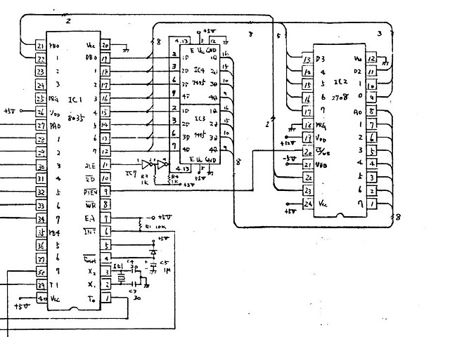
The upper two address lines of the EPROM, A8 and A9 are controlled by two bits of I/O port B. This arrangement may be used as a bank switch to select different sections of the EPROM in order to play the relevant tunes at various points in the game, coin up, laser base hit, game over etc.
Checking the signals around the controller IC and EPROM, the power supply rails are correct, clock signal present, bidirectional address / data signals all active, EPROM select line toggling so no obvious issues - but it intrigues me that the data outputs from the EPROM are connected to the same bus which outputs the addresses, is any of this activity on the data bus actually coming from the EPROMs data outputs?
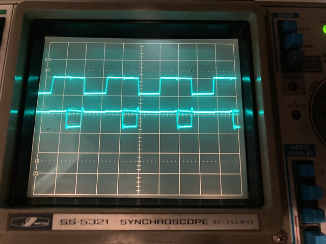
To verify if the EPROM is outputting data we can use the oscilloscope and view the /PSEN (Program Store enable) signal from the 8035, which connects to the /chip select line of the 2708. When this signal is low the EPROM should be outputting data on to the data bus. Comparing this select signal (upper trace) to each of the data outputs from the EPROM (lower trace) it becomes clear that whenever the EPROM is selected each data line is always HIGH. This EPROM has either failed or is blank, outputting the data byte FF hex for every address input.
Borrowing the EPROM from the spare sound PCB to check, the additional sounds and tunes come to life but there is a mismatch, the incorrect sound or tune is playing for each event in the game play. I have seen this before while experimenting in MAME, swapping sound ROM versions between Space Fever and Hi Splitter ROMsets to see if the sounds were interchangeable. The answer was no and here is the proof on actual hardware, it turns out the spare sound board was fitted with a Hi Splitter sound EPROM.
The label on the EPROM from the spare sound board has the letters NS printed on it. As I'm currently running the CPU board with a single EPROM containing both Space Fever and Hi Splitter ROMsets it's easy to switch the game and re-test the sounds. Sure enough the Hi Splitter game now runs and plays with all sounds present and correct.
I've been working on two sound PCBs for a Nintendo Space Fever board set. The original one is working now having repaired some damaged tracks and replaced a couple of broken resistors, a few electrolytic capacitors just as a precaution then found that the sound EPROM was not working. I borrowed the EPROM from the spare sound PCB just to confirm, all that remains is to program and install a replacement EPROM.
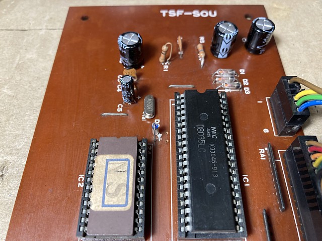
On to the spare sound PCB now, the tracks on this board are in much better condition than the original PCB so the best alternative is to repair this PCB and use it as part of the set. Although the PCB itself is in better condition some of the components have a bit of corrosion and will need replacement, starting with the 6 MHz crystal. I've just received a new one from order, this one is in a low profile package but otherwise equivalent so we'll solder it in place and see if the sounds are working.
Having done that and testing, none of the sounds are present. We'll start by diagnosing the signals around the D8035 microcontroller IC, having fitted a new crystal there should now be some activity. Looking with the oscilloscope there is now a good 6 MHz signal where the crystal connects to the IC but no output or activity on the data lines, control signals etc. All of the input lines from the I/O PCB also appear to be held low by the microcontroller which seems incorrect.
Swapping the known working D8035 IC from the original PCB (fortunately the Microcontroller and EPROM are both socketed on these PCBs) just to confirm, the sounds all come to life including the three sounds which are created by the SN76477 complex sound generator IC. It seems the control signals being held low was also preventing these sounds from working though they are otherwise independant of the microcontroller operation.
So this board is now working. For the other PCB I'll need to order a replacement D8035 IC and wait for it to arrive, they're well and truly obsolete but should be obtainable at least. Meanwhile I'll continue with cleaning and a general tidy up of both sound PCBs, replace some corroded looking capacitors, check and maybe replace some of the volume trimpots etc.
The Nintendo Space Fever Colour PCB set is now repaired and working including one sound PCB also repaired, complete and working while the second sound PCB is repaired and just awaiting parts to complete. That one will feature in the next repair episode.
Meanwhile as the intention is to keep this PCB set original but running the High Splitter version of Space Fever all that remains is to reprogram and refit the original set of 2708 EPROMs. That's a story in itself as I'm currently working on an adaptor for my existing EPROM programmer to be able to read and reprogram the very obsolete 2708 type EPROM.
To be continued...
Web Resources (External Links) -
Nintendo Space Fever Colour repaired PCBs test running Hi Splitter ROMset - YouTube
Space Fever (colour version) interconnection pinouts - CrazyKong.com
All images and text on this website are Copyright.
Contact: jbtech at telstra dot com