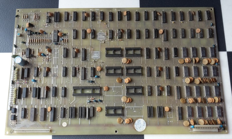
Shuttle Invader PCB, Omori
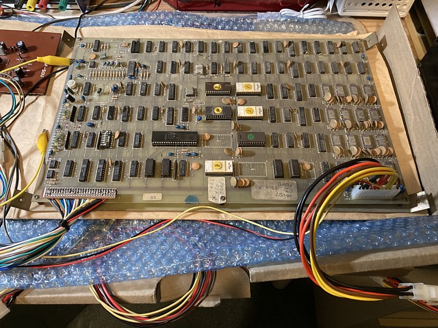
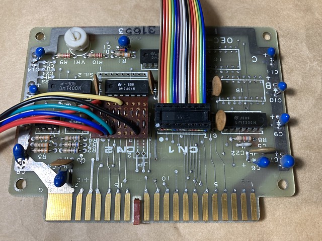
I purchased this Omori Shuttle Invader PCB some time ago, just to see if it could be brought back to life. It's missing several parts but otherwise in reasonable condition so the initial challenge will be to 'fill in the blanks'.
And there are plenty of blanks, both onboard the PCB itself as well as in the Omori Shuttle Invader story generally. Not a lot of details have been unearthed about this obscure Japanese Invader 'clone' and I have discovered a few inaccuracies amongst the machine's existing 'knowledge base'
This PCB would have once belonged to a 'Shuttle Invader' machine, manufactured in Japan by Omori Electric Co. around 1979. As far as I know all such machines were of the Cocktail variety, using a monitor with vertical orientation and capable of flip screen, alternating two player operation.
Most descriptions I have read suggest the game exclusively used a Black and White screen with gel type coloured strips affixed but I've since concluded both Monochrome and Colour variants existed, the latter using a separate small PCB connected to the main by a ribbon cable to electronically apply a colour 'overlay' to the Black and White image. This is similar to the method used by Taito on their Space Invaders Colour machines.
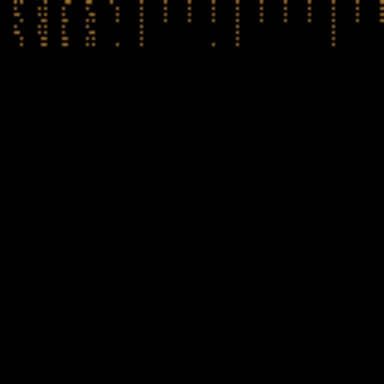
The additional PCB was marked OEC-4A and contained a 256 x 4bit Bipolar PROM. Using the program 'YY-CHR' to view the contents of the PROM file graphically (left picture), there is a simple pattern which represents the colours enabled for each segment of the video image. Only 3 bits are used for each segment, representing the three CRT primary colours. The majority of the screen just has a single colour selected, presumably green while other areas are red or a combination resulting in yellow, magenta or cyan.
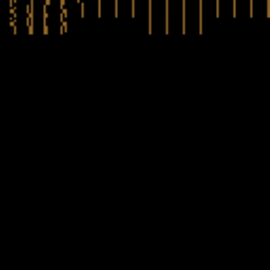 |
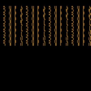 |
Comparing that with the contents of a Taito Space Invaders colour PROM (right picture) the Taito PROM contains more data, the screen being divided up into more, smaller segments and there are two colour PROMs for the Taito as Player 1 and 2 each have their own colour overlay with slightly different colour selections but the principle is obviously the same for both machines.
As I only have the main PCB to work with I'll be attempting to repair the game as a purely Black and White unit unless I come across a matching colour overlay PCB at some point or decide to fabricate this small additional PCB from scratch, using original spec. componentry where possible.
I've had a bit of luck with the Shuttle Invader PCB project, sourcing a printed manual for the machine - which was apparently distributed by LAI in Australia at the time. This will make all the difference as the chances of repairing the PCB were not good with many missing and unidentified components and apparently no circuit diagrams available online.
How a number of obscure Japanese Invader 'clones' such as these made it to Australia in the first place is an interesting story, beginning with the introduction of Taito's Space Invaders in 1978. That machine rocked the arcade industry in Japan which had previously featured mostly electro mechanical or TTL based 'bronze age' video arcade titles.
The reaction to Space Invaders was enormous, demand to play the new title being so great in Japan that entire arcades soon sprang up, filled with dozens of Space Invader machines alone and an urban myth suggests the machines even caused a national shortage of 100Yen coins.
Not wanting to miss out on the 'Invader Boom' other manufacturers scrambled to build similar machines, from Logi Tec Co's almost identical 'TT' cocktail version to Nintendo's Space Fever and many others. Most of the Invader style machines were either Black and White, often with coloured 'gel' strips attached to the screen or colourised versions applying an electronically generated colour overlay to the originally monochrome graphics.
Within a year or so new machines were released with improved colour graphics and new challenges such as Namco's Galaxian and gradually the demand for Space Invaders waned. The 'Invader Boom' in Japan was over but the 'Golden Age of Arcade Video Games' had well and truly begun.
Imagine the surplus of Space Invader machines and clones when this occurred, arcades replacing them to satisfy demand for newer games. Meanwhile other countries in the Asia Pacific region such as Australia were still catching up with strong demand for Space Invaders and welcomed both new and pre-loved Japanese machines.
Some conversion was required, from Japan's 100V AC supply to 240V and 100Yen to 20c Aus. currency, adding instruction cards in English so it appears distributors such as LAI and even Taito Australia imported surplus machines and performed the necessary conversion for resale here.
In time, many of the more obscure models such as Shuttle Invader were considered less valuable than the 'genuine' machines and if they stopped working were most likely scrapped or the cabinets converted to other games so complete 'clone' machines in original trim are now rarer than ever.
The loose PCB which I have was probably removed from such a machine, stripped of useable parts such as CPU, EPROMs and even Crystals and narrowly escaped from being sent to land fill. Now it's time to try and return it to the land of the living.
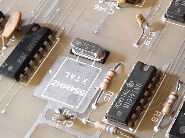
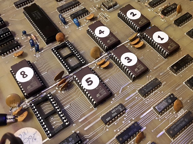
The first task will be to replace missing components: 8080A CPU - already have. 18MHz Crystal - already have one, with a broken pin but can solder a wire onto. 5.545 MHz Crystal - have ordered the nearest available frequency I could find, 5.5296 MHz which is within 0.3% of the original and should work OK. It's a low profile, surface mount type but can be fitted to this PCB by soldering on leads if required.
Missing ICs; 8216 Bi directional bus driver IC x 4 - have a batch on order. 74LS30 and 74LS155, ordered. 14 and 16 pin IC sockets, 50k trimpot - already have.
And now for the EPROMs, Shuttle Invader uses 6 x 2708 1k x 8bit EPROMs, unfortunately I don't have any 2708s in stock or a suitable programmer for that type. I could probably order some old stock ones and adapt my existing programmer, adding the extra +12V and -5V supplies required by the 2708. Alternatively with slight alteration to the PCB tracks I could substitute 4 x 2716 EPROMs or 2 x 2732 EPROMs.
Another alternative and my preferred option at this stage would be to make up a small adaptor with a single 2764 EPROM which could contain the entire Shuttle Invader ROMset. Even better, a single 27128 16k x 8 bit EPROM could accommodate both the Shuttle Invader and the Sky Love ROMsets, with a small switch to select either 8k ROM 'bank'.
This adaptor would be installed without any modification to the existing PCB tracks so could be entirely removed if required to return to original configuration.
It's hard to imagine a game more obscure than Shuttle Invader but apparently Omori made a second game based on similar 8080 CPU hardware called 'Sky Love', before moving on to Z80 CPU based games. I'd like to try and get both of these games running on this PCB if possible.
I've made good progress with the Omori Shuttle Invader PCB repair project. The parts I ordered to replace missing items have all arrived so I can install them and set the PCB up to test on the bench.
Fitting the two crystals, the new 5.5296MHz item is a surface mount package, turns out this is the same as the through hole component except an insulating spacer had been added and the two pins flattened over during manufacturing to allow it to be surface soldered. Carefully straightening the legs allows it to be soldered into the existing PCB through holes. I've left the insulator in place to prevent the metal case shorting the PCB tracks underneath as there is no solder mask on this PCB.
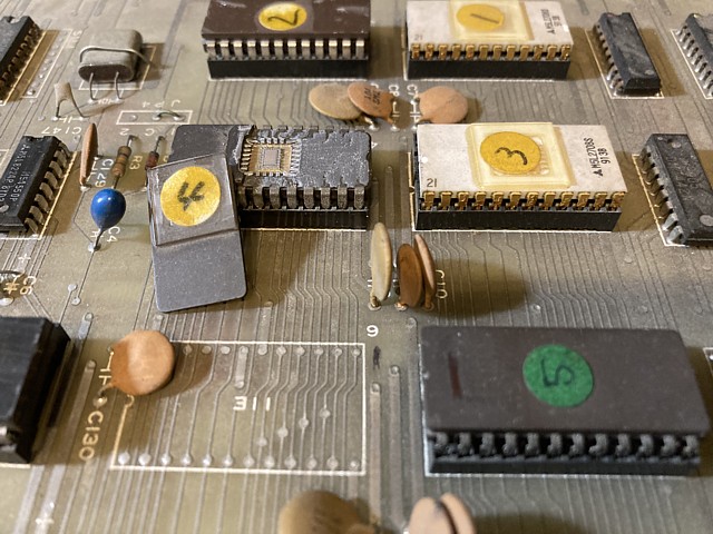
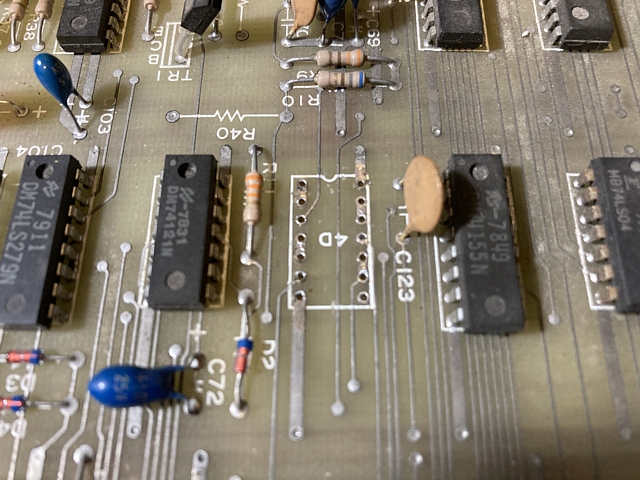
The 8080A CPU and 8216 buffer ICs simply plug in to existing sockets and I'm fitting the two TTL ICs with new sockets. The PCB was a bit scorched under the 74LS155 so there may have been a short circuit in the previous component which had already been removed. I've cleaned the area as well as possible before soldering the new socket in place.
I had a change of heart about the EPROM configuration, while a single 27128 would accommodate the entire Shuttle Invader and Sky Love ROMsets and would be fine for testing purposes it would not be period correct for such an early PCB. Instead I've decided to install a full set of 2716 EPROMs with the Shuttle Invader program in the upper 1kByte of each IC and the Sky Love program in the lower half.
This will require a total of eight 2716 EPROMs, only six are initially required for Shuttle Invader but the Sky Love ROMset originally used eight 1k x 8 EPROMs so I've also programmed EPROMs 6 and 7 and installed new sockets in those positions. Substitutng 2716 EPROMs for the earlier 2708 components only requires slight modification to the PCB tracks and I've added a pullup resistor to the additional address line which will allow a switch to be added later to select the Sky Love program.
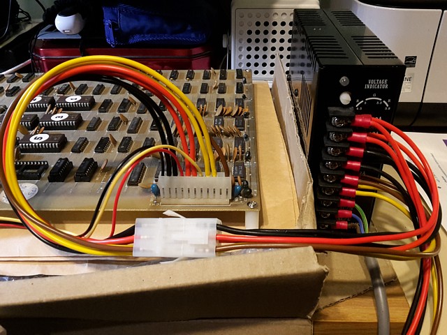
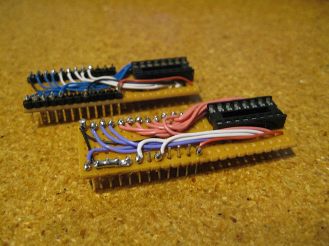
Having fitted all the parts the next step is to make up a bench test lead to suit the unique connections to this PCB. There is a Molex style header for the Power Supply Voltages, I already have some suitable connectors (which I purchased for the Chase H.Q. PCB repair) with some trimming as the header on the Shuttle Invader PCB only uses 11 positions instead of 12, 10 pins plus one key space.
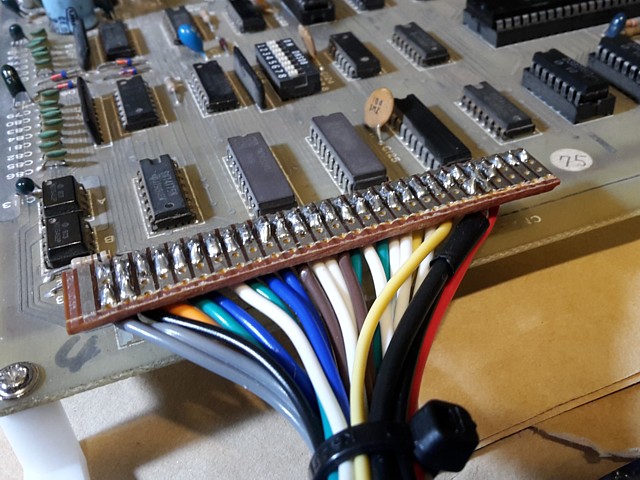
There's also a 25 way PCB header for control inputs, Video and speaker outputs. It's similar in pitch to a common SIL PCB header but the pins are flat instead of square and I don't have a suitable mating connector. For testing purposes I've adapted a 28 pin dual wipe IC socket, cut in half and arranged into a single row using a small strip of Veroboard for wiring connections.
Adding some switches for testing of control inputs - the Shuttle Invader circuit requires both Normally Closed and Normally Open contacts to be connected for most inputs which use a flip flop style debouncing circuit. It adds a fair bit of wiring and means I can't just use my regular Quickshot joystick for testing inputs. Instead I've made up a little circuit board with ten small microswitches having Single Pole Double Throw (S.P.D.T) operation.
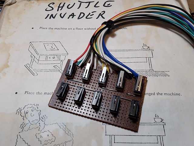
The switch functions are: Reset, P2 Fire, Left, Right, 2P Start and below: Coin, P1 Fire, Left, Right, 1P Start.
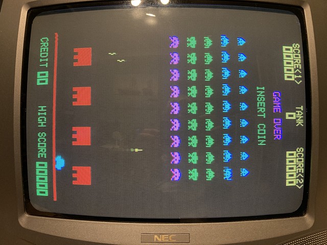
I've tested for shorts between any of the Voltage rails and ground with a multimeter and they all seem OK so, with all of the connections made it's time to power it up and see what we get...
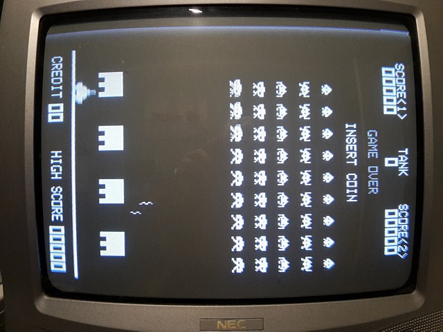
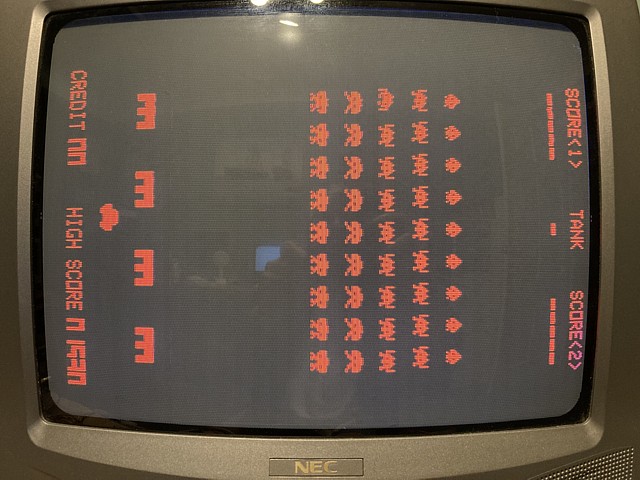
Amazing! The game is running, even has sound. The Video levels look wrong but it could be soooo much worse, all I've done so far is replace missing components. I'd better have a look at those Video levels.
It's no surprise that my NEC TV monitor is having trouble with the Video signal, there's about 5 Volts of it and most of that is sync. A standard composite Video signal is 1Volt, 0.7V Video above 0.3V Sync. Looking at the Video output stage on the Shuttle Invader PCB there are some component changes from the circuit diagram with some load resistors omitted and output resistor replaced by a link.
It could be that this game PCB was used with the optional colour overlay PCB in which case the Monochrome Video output would have been used as the source of sync for a colour arcade monitor (that would explain the unusually high sync level and muted video on that output) or it could have been set up for a non-standard signal level to suit a particular Black and White TV monitor.
Early Black and White games such as this often used an AV modded TV set for a monitor and depending how the Video was inserted into the signal path a specific level may have been required. More modern TV monitors on the other hand are designed around a standard 1Volt composite Video input signal.
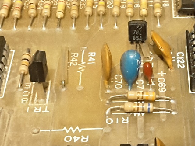
Anyway, changing R10 to 120 Ohm, installing 330 Ohm R40, changing output resistor R42 from zero to 68 Ohm and adding 560 Ohm load R41 returns it to original configuration. R41 was actually listed as 510 Ohm but 560 is close enough as it is just a load for the common Collector output transistor TR1 and won't affect the gain - Common Collector (a.k.a. Emitter follower) stages are usually used as buffers and have a unity gain.
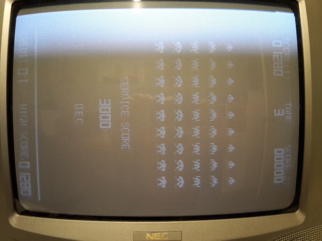
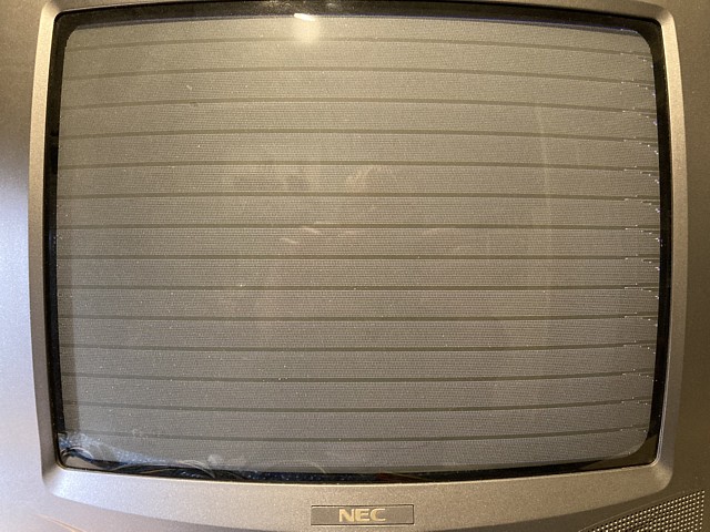
That's improved the situation a lot but we're still getting about 3 Volts of Video. That white band at top of screen isn't Video noise or hum but a clamping problem, after Vertical sync the black level is set way too high but eventually recovers. Hopefully padding the signal down to correct levels may help with that.
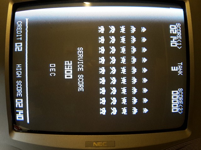
So, increasing the output resistance from 68 Ohm to 270 Ohm by trial and error reduces the signal to a 'standard' 1Volt level. The image is much improved and is fine for this test setup but might need trimming if an original Black and White TV monitor is used at some point.
Moving on to test the game play, all appears to be working except for a missing 'UFO flying' sound. All the other sounds are present though slightly different to the more familiar Taito (or Midway) versions of Space Invaders sounds including the Invader marching sound which in this case seems to be a single note rather than the famous 4 note progression.
Interestingly, even though the game had a full set of sounds on board there was an additional sound PCB added to some machines. I'm guessing the idea was to replace the slightly 'different' original sounds with something closer to Space Invaders in the hope that if the game sounded more like a 'genuine' machine more people would be attracted to play it.
That's just speculation really though the additional sound board is documented and had the board number OEC-5. It connected directly to the speaker, replacing all on-board sounds and was controlled via a ribbon cable from the main PCB connector CN4. It appears this particular PCB was never paired with the additional sound PCB as the DIP socket at CN4 was not populated.
So, all that remains is to troubleshoot the missing UFO flying sound and then try to also get the Sky Love game running on this PCB, if possible.
My Omori Shuttle Invader PCB is running now, the only issue appears to be a missing 'UFO Flying' sound. Unlike Taito's Space Invader sound hardware which uses a SN76477 Complex Sound Generator IC for that particular sound and a combination of logic and analog ICs for the rest, the Omori on-board sound hardware uses a single SN76477 (controlled by CPU port #fe) for the Laser Base firing and explosion sounds as well as the 'Invader hit' and 'UFO hit' sounds. Those last two are really just the same sound with a different duration in this case.
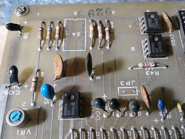
The remaining sounds on the Shuttle Invader PCB are generated by logic and analog ICs and controlled by CPU port #fd, being the 'UFO flying', 'Invader marching' and 'bonus Laser Base' tones . Of those, the 'UFO flying' is the more complex using two 555 timer ICs and a LM1458 Op Amp to modulate a high pitched tone with a lower frequency causing a warble effect. (Note: there is a 'spare' position in this section of the PCB where a 556 dual timer IC can be fitted instead of the two 555 single timer ICs).
The output of the first 555 timer IC is fed to the control input of the second via the LM1458 Op Amp which appears to reshape the waveform from a square wave to something more like a sine wave signal. There is a small trimpot connected to this stage which I originally assumed to be a sub volume control but actually sets the DC level of the modulating waveform. It turns out this was the problem as the DC level needs to be within a certain range or there will be no sound output at all from this section.
Having finally realised that, the solution is simple - start a game, wait for the UFO to appear on screen and adjust trimpot VR1 until the UFO flying sound is clearly heard. That done the Shuttle Invader PCB is now fully working.
Well, that was too easy so to complicate matters I'll move on to trying to get the Omori 'Sky Love' game also running on this PCB. I know from reading the description within the MAME driver for both games that their hardware was similar but apart from that and a game flyer can find no other documentation, technical details, photos or indeed any reference to an actual Sky Love machine or PCB by searching online.
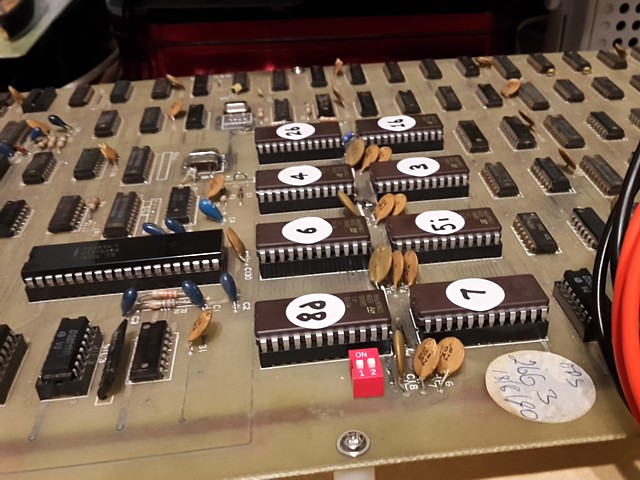
Undeterred, I'll proceed by first fitting a little DIP switch to a conveniently empty space on the PCB, to select the Sky Love ROMset. I had already programmed a full set of 2716 EPROMs with the Shuttle Invader software in the upper 1kByte of each and Sky Love in the lower half, adding a 10k Ohm pullup resistor to the additional address line A10 to default to Shuttle Invader. Adding the DIP switch to ground selects the Sky Love ROM bank instead.
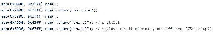
Before I can try it out however I need to resolve a potential issue with a difference in the memory map for the two games, according to the MAME driver. (Thanks as always to the MAME Dev. team for this invaluable resource, not just for keeping the games software alive but also as a reference for troubleshooting and reviving actual hardware). I'll include a few brief excerpts here to illustrate the process with this project.
According to the memory map, in addition to the 8kByte of ROM space addressed from 0000 to 1FFF Hex, 8kByte of Dynamic RAM (Comprising 16 x 4027 4k x 1 bit RAM ICs no less) from 2000 Hex to 3fff there is 1kByte of static RAM, being 2 x 2114 1k x 4 bit ICs. On the Shuttle Invader PCB these are addressed from 4000 Hex to 43ff but apparently in the Sky Love software this RAM is addressed from 6000 to 63ff Hex.
This would render the Sky Love software set incompatible with the Shuttle Invader PCB, at least without some modification it would seem. To confirm I'll refer to the hardware address decoding for Shuttle invader.
The 74LS139 at location 16D on the Shuttle Invader PCB decodes the address bus into 8k blocks, the first is further divided by the 74LS42 at location 15D which generates a select signal for each 1k EPROM. The next range of addresses from 2000 to 3fff Hex select the Dynamic RAM and the range from 4000 Hex goes on to select the Static RAM. The fourth output of the 74LS139 on pin 9 which corresponds to addresses from 6000 Hex, goes nowhere.

In order to run the Sky Love program, the track from pin 10 of the 74LS139 could be cut and instead connected to pin 9 but my intention is to make this PCB compatible with both programs. A switch could be added to the select line but would need to be a double throw type to connect either select signal to the Static RAM depending on which ROMset is in use.
Another option would be to edit the Sky Love ROM files, changing the address selected whenever the Static RAM is accessed but there would be hundreds of instances in the full program where the Static RAM is accessed and each would need to be re-addressed. A more elegant solution would be to combine the select lines for the two address ranges in hardware making the RAM accessible at either address range. This is the 'mirrored' approach as noted within the MAME driver.
The select signals for the two address ranges cannot be simply joined together. This would be possible for two Open Collector signals but for 'standard' TTL signals an additional logic gate is required to combine them. Fortunately on most PCBs which utilise logic components there are unused gates on some ICs which can be pressed into service.
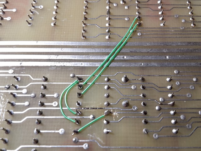
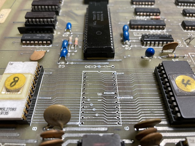
Sure enough, inspecting the PCB for logic ICs with unconnected pins it turns out one half of the 74LS20 Dual 4 input NAND gate at position 17E is unused, perfect! Inserting the additional gate into the logic flow as follows (also tying the two unused inputs high), combines the select signals for the two address ranges.
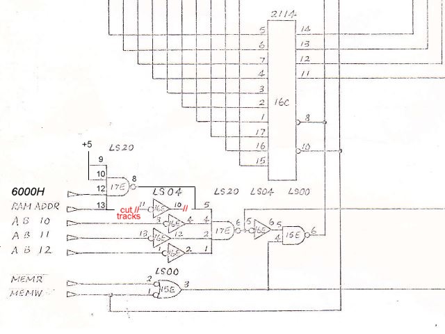
And this is how it looks on the actual PCB, not too bad I'd say...
So, setting the DIP switch off to select Shuttle Invader and powering up to test, that game still runs fine. Power off again and turning the DIP switch on to select Sky Love; on power up we get a low tone from the speaker but apart from that - nothing. There would appear to be some other factor preventing the game from running at all.
At this point I'd like to see what is occurring at a software level so I've combined the eight individual Sky Love ROM files to create a single 8kByte binary file and run that through an online disassembler in order to read parts of the program in assembly language.
I've selected 'Z80' as the CPU type rather than '8080' as I'm (slightly) more familiar with the Z80 instructions. The Z80 was developed by Zilog using Intel's 8080 Instruction set as a starting point and expanding upon those, effectively making the 8080 instructions a subset of the Z80's. So the assembly language shown is in Z80 syntax, apologies to any 8080 purists.
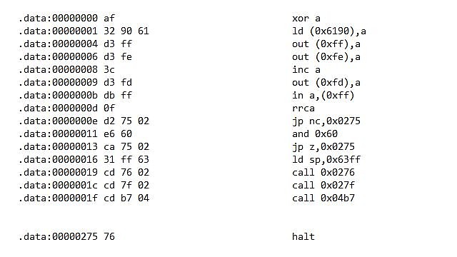
This little excerpt starts at the beginning of program, zeroing the accumulator A (XORing any value with itself results in zero, a quick way to make sure the accumulator begins at 00). Memory address 6190 Hex is then initialised to zero and output ports #ff and #fe cleared. A is then incremented and output port #fd set to 01 which explains the low tone from the speaker, actually the 'invader marching' tone is selected here and left on.
That is the first indication that the Skylove program is not fully compatible with the Shuttle Invader sound hardware, more on that later. Next the input port #ff is read. What happens next is interesting, first the rrca command shifts each bit which was read from the input port to the right with bit 0 setting or clearing the 'carry' flag. If that happens to be zero the program jumps to address 0275.
Next, the accumulator value is ANDed with 60 Hex (all bits except bit 5 and 6 zeroed, if bit 5 and 6 were both zero as well the program also jumps to address 0275. At that address there is a HALT command, ending the game before it has even begun. Harsh! Those two bits actually derive from bits 6 and 7 of input port #ff, the rrca command having shifted them prior to testing.
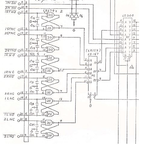
So what's actually being checked here and why does it 'fail'? Reading port #ff enables the 74LS240 inverting latch at location 3f which reads the status of control inputs. Bit 0 is actually not used and in the diagram is connected to the active low select signal so its output would always be high when read.
On my PCB however this input is left to float high so the output would actually be low, triggering the halt condition. There appears to be a little notation next to that connection on the diagram so perhaps it was a revision, in any case adding a link from pin 2 to pins 1 and 19 as drawn will correct that issue.
Bits 6 and 7 read the Player 1 / 2 Right and Left inputs respectively. At rest the Normally Closed contacts are both connected to ground so the corresponding inputs of the 74LS240 at position 3f would both be high resulting in the relevant outputs both being low.
That is the second condition which would trigger a jump to the HALT instruction however it occurs to me that if the Player 1 Left or Right control is simply held on during power up then this condition would not be met and the game should run so, trying it out we have some progress at last!
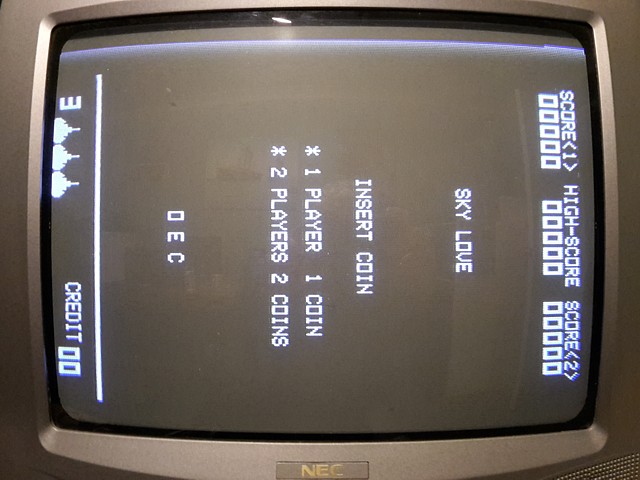
That little workaround did the trick! The game is running albeit with sounds which are all wrong and the controls seem backwards. The laser base moves to one side by itself and when the Left and Right controls are operated they seem to have the opposite effect. Let's have a look at the section of the MAME driver which deals with the control inputs for Sky Love:
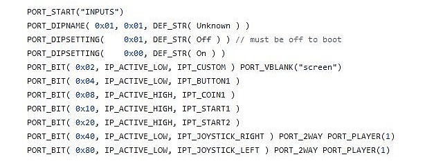
Firstly there's a note about bit 0 which must be off to boot, we've already encountered that issue. The Player Left, Right and Fire inputs are defined as active Low whereas other inputs are shown as active High. This is unique to Sky Love as the equivalent definition for Shuttle Invader shows all inputs as active High.
I'm guessing the controls for Sky Love were inverted by swapping Normally Open and Normally Closed connections on the control switches. I'd like to leave the controls intact however and correct the issue in software so the original Shuttle Invader software will still run correctly.
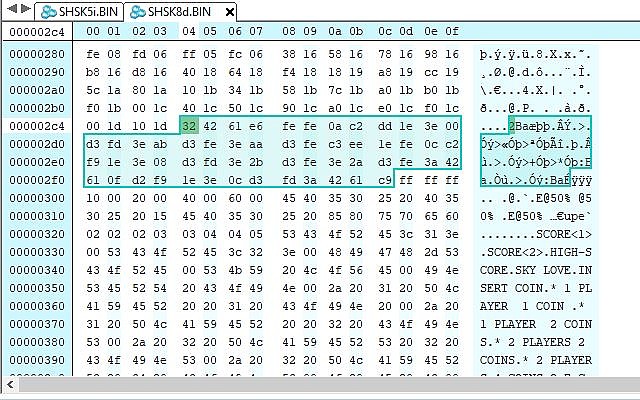
Searching the disassembled 'skylove' program file now for other instances where the control inputs are read using the instruction 'in a,(0xff)' there's only one and it's a little subroutine:
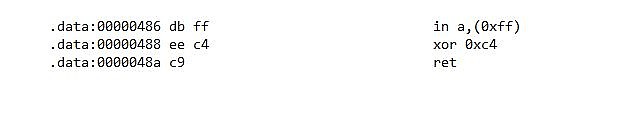
Immediately following the read of the input port there's an XOR instruction against a value of C4 which would have the effect of inverting bits 2, 6 and 7 which are the player Fire, Right and Left inputs. By skipping this step, substituting a couple of NOP instructions or simply changing the value from c4 to 00 the inverted controls are fixed.
So now the game runs and plays correctly, the controls working but that hasn't corrected the halt on startup if the controls are at rest. The easiest way to avoid that issue is to simply change the jump address from 0275 (the location of the HALT command) to 0016 which is the next program instruction so the program will continue normally regardless of the position of the controls at startup.
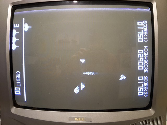
Sky Love is an unusual game with a similar laser base to Shuttle Invader but the invaders marching in formation are replaced by an assortment of UFOs and Rockets moving independantly. The rockets resemble the player ship from Asteroids, which stop mid flight and rotate before zooming off in a different direction. There are also occasional Missiles descending from above which cannot be destroyed and must be avoided.
This program probably stretches the hardware to its limits as there are no sprite layers as in later machines, all the action takes place within the overall bitmap screen space.
The sounds in Sky Love must have been quite different to Shuttle Invader as there seem to be many sound events triggered within the program including game start and end, switching player etc. as well as the usual firing and explosion events. I'm guessing the original Sky Love sound hardware may have even played little tunes, something like Nintendo's Space Fever which played a few bars of the Star Wars theme when coined up and strangely, 'Song of Joy' at Game Over...
It won't be possible to implement correct original sounds on this hardware for Sky Love as there must have been a unique sound PCB used in conjunction with the main CPU board and my chances of finding one or even relevant documentation are virtually nil. All I can do within the limitations of the Shuttle Invader hardware is identify the sound events in the Sky Love program and alter the code as required to play a Shuttle Invader sound, where a suitable alternative exists.
The first step is to identify sound events, characterised by 'out (0xfd)' or 'out (0xfe)' instructions then alter to trigger a known sound such as the 'bonus Laser Base' sound by outputting a 02 value to port #fd. Once done it's a case of listening for that specific sound while playing the game and noting when each occurs.
Having found the Laser Base firing and explosion sounds, Rocket hit, UFO hit and finally the Missile start and end events I can substitute codes for the Shuttle Invader sounds. Most of these require 2 or 3 codes to be sent, two to define a one shot sound with a set duration and the third to set the 'noise' frequency which defines the difference between a firing or explosion sound or to begin or end the 'UFO flying' sound which I've assigned to the Missile in Sky Love.
To fit the additional codes into the existing program I've identified a couple of 'blank' spaces in the existing ROMset, substituting a jump instruction to the additional code space and returning from there. To avoid affecting any of the existing program I'm using the accumulator A as my only variable and re-loading its previous value before returning.
Having done all that I'm really happy with the result. Both games play well on the one PCB and sound 'right' though I'll probably never know what the Sky Love game would have originally sounded like with its own sound PCB. The Shuttle Invader game plays and sounds 100% correct.
The only unusual behaviour I've noticed while playing Sky Love on this PCB is some flickering of the enemy rockets and UFOs which at first glance seemed like a possible RAM problem but it is not evident when running Shuttle Invader.
I now think the flickering is a bit of ghosting, when the moving objects are not all fully written to screen RAM within each frame interval. This flickering doesn't show up when running the game software in MAME but in MAME the video is not output in a scanned sequence, line by line.
In a slight variation on the 'Chicken or the Egg' riddle, this arcade machine repair began as just a game PCB.
Some time ago I bought an Omori Shuttle Invader PCB in an incomplete state just to see if I could get it working. Having done that successfully the question arose; what to do with it now? It's not like a later, JAMMA standard PCB which can be placed into any generic JAMMA wired machine, the control wiring using both 'normally open' and 'normally closed' switch contacts being fairly unique to this machine as far as I know.
That's not to mention the fact that this was a Black and White game which requires a separate colour overlay PCB in order to work with a colour monitor, which I didn't have at the time. The best solution seemed to be to make or adapt some existing cocktail machine cabinet with the necessary monitor and controls to run it.
I had dismissed the possiblity of finding a correct cabinet to install my working PCB into. Being a Space Invader clone and not particularly valuable at the time, most of these machines would have been scrapped or converted to other games at some point when they stopped working so complete machines with original internals by now are almost extinct.
Imagine my surprise when I received a message from a friend asking 'Weren't you looking for a Shuttle Invader?' with a link to one which was currently for sale. It was not too far away, not too expensive and not working but did seem complete and the most likely issue was its original game PCB, the very part which I already had a working replacement for.
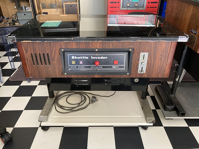
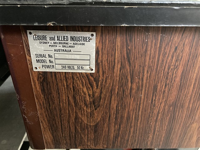
So here it is. Made in Japan by Omori Electric Co., Ltd and retaining the Japanese script on its control panels. These were imported into Australia by LAI, converted with 240V step down transformers and instruction cards printed in English. It carries the usual LAI identification plate on the cabinet.
Inside it looks pretty original with the transformer providing AC secondary Voltages for the linear power supply (top right of photo below) as well as an isolated 100V AC supply for the colour monitor. To the bottom right of photo is the step down transformer added for Australian 240V mains supply.
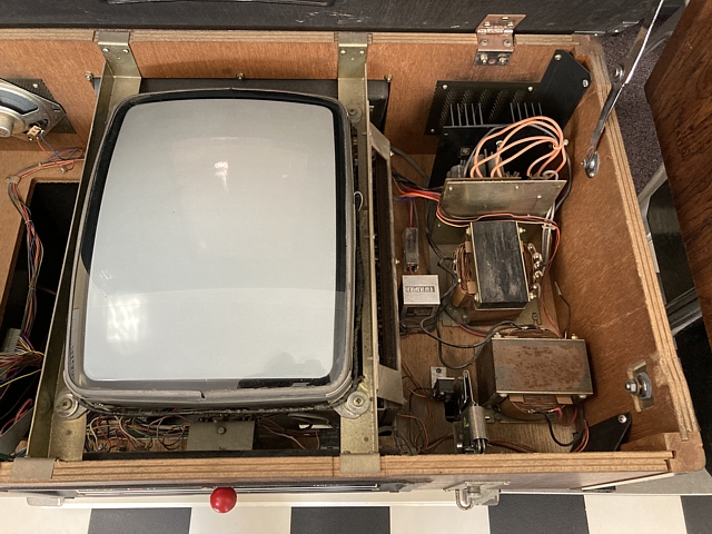
Here I've already removed the original game PCB which was sitting loosely in position, still connected to power and control wiring. When powered on very briefly there was no sign of activity apart from a few small lines on screen, these did seem to show that the original looking Toei monitor is still working at least. The CRT itself has no screen burn and may have been replaced at some stage.

Also seen in the photo above is the elusive colour overlay PCB (part No. OEC-4B). It turns out the 16way ribbon cable which connects it to the game PCB wasn't plugged in so there was no hope of a proper video output even if the game PCB had been working (which it wasn't). So the PCB had probably been removed for testing at some point and just put loosely back in place when it all became too hard.
Even though I already have a working Shuttle Invader PCB (which now also runs Omori's 'Sky Love' game) I'll still test this PCB on the bench to see what might have gone wrong and fix it if possible. It never hurts to have a second game PCB as a working spare.
On initial inspection one obvious issue was some clear packing tape had been placed over the top of the 2708 EPROMs. Carefully removing that the reason was revealed; one of the EPROMs ceramic packages had broken, a layer having come adrift along with the attached quartz window which allows UV erasure and the packing tape was just holding it in place.
Fortunately, none of the fine internal wires which connect the IC wafer to the external pins seemed to have been broken when the chunk of ceramic came adrift so, after using my EPROM programmer to verify its contents against the known Shuttle Invader ROM file to confirm the component was still working I carefully refitted the broken section of the IC package with a drop of acrylic adhesive.
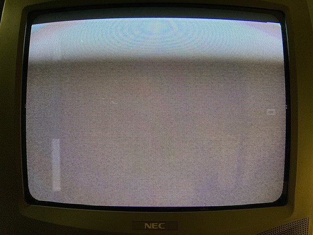
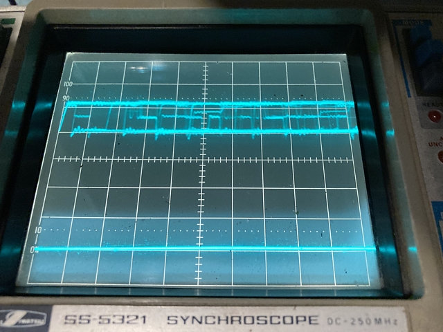
Powering the board up on the bench there is just a faint pattern on screen accompanied by a high pitched warbling tone from the speaker which I recognise as the 'UFO flying' sound being stuck on. At least there is some sort of sync signal present on the composite video output or the NEC TV monitor would just display a blue screen.
Those dark horizontal bands seem wrong though and may be spurious, incorrectly timed sync pulses. I'll have to check the composite video output signal with my oscilloscope to see if there is a problem with the sync timing.
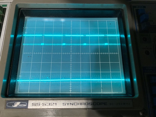
Sure enough there is a problem with the timing of the vertical sync pulses. Instead of repeating at a rate of 60Hz, approximately every 16 milliseconds they are occurring at just over 1 millisecond intervals, a frequency of nearly 1kHz. The monitor does not respond to vertical sync outside of a narrow frequency range so the additional pulses are seen on screen without triggering the vertical retrace.
The vertical sync frequency appearing to be 16 times too high is significant; the horizontal and vertical timing signals are derived from the 5.545 MHz clock frequency using a series of 74LS161 binary counters. Each counter has 4 outputs which effectively divide the input frequency by 2, 4 8 and 16. At the completion of each 16 count cycle the carry output enables the next counter in the cascade to increment by one count, dividing that frequency further.
With some additional logic to reset the count, the second 74LS161 in the sequence produces the horizontal sync and blanking signals which are then divided further by counters in positions 14A and 14B to produce the vertical timing signals. Checking the 74LS161 in position 14A, none of its binary outputs are toggling and the carry output appears to be stuck at about 2 Volts. This is causing the final counter in position 14B to increment on every clock pulse rather than once in every 16.
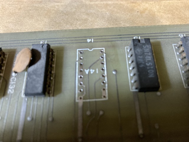
Having removed the faulty 74LS161 from position 14A then installing a socket and a new IC the vertical sync signal now appears correct and the monitor shows a stable, blank screen. Moving on to test the signals around the 8080A CPU, power supply rails and clock signals appear present and correct but the reset signal does not appear to pulse high on startup or when the reset input is manually selected.
Tracing the reset signal via the 8224 IC in position 9D to the 74LS38 open collector NAND gate in position 4D, used here as an inverter to provide an active low reset signal for other parts of the circuit - its output appears to be stuck in the high state. The resulting signal which reaches the CPU via a 74LS04 inverter in position 9F remains low, never resetting the CPU.
Removing the faulty 74LS38 IC from position 4D then installing a replacement along with a new socket, the power on reset signal now appears correct and there is some CPU activity evident on its address outputs and data I/O pins. After reset the first action of CPU will be to read instructions, in this case from EPROM.
Checking the signals around the 2708 EPROM at address zero, in position 13C its chip select input pin 20 is not active. Tracing that back via the 74LS42 address decoder in position 15D it appears that is due to address line AB10 being stuck high. Initially suspecting a faulty 74LS244 address buffer in position 8D the fault turned out to be an open circuit connection from the CPU pin 1 to the buffer input, pin 13.
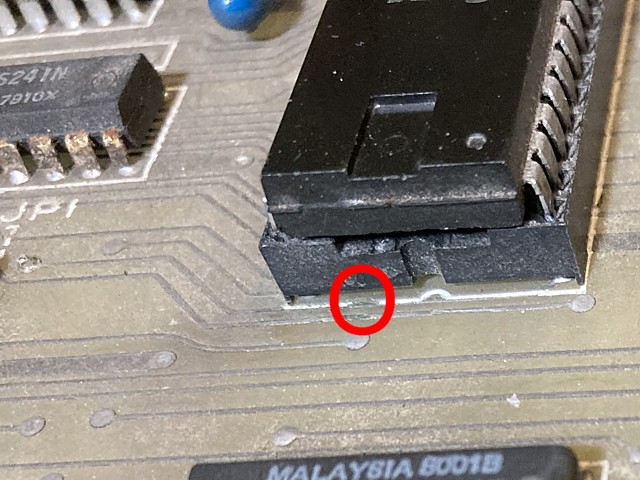
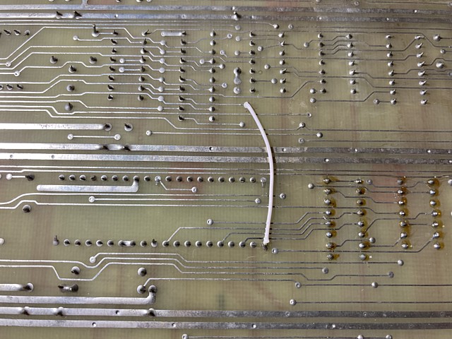
Upon closer inspection the PCB track had a patch of greenish corrosion on the component side where it emerged from under the CPU socket. Rather than attempting to bridge the inaccessable section on the component side I opted to add a wire on the solder side from the CPU pin 1 to a via (plated through-hole) which leads to pin 13 of the buffer IC.
That gets the /CE signal to the EPROM working and it appears to be outputting data onto the bus when selected. Tracing back to the 8216 buffers in position 15F and 16F the data bit DBM6 is noticably less active than at the EPROM so there appears to be another connection issue.
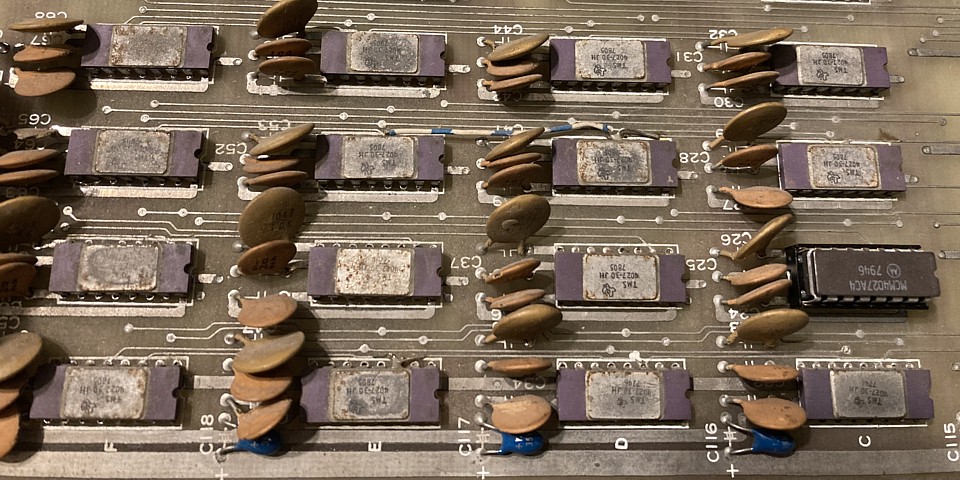
It turns out that is caused by a corroded pin 16 of the 2708 EPROM, which broke off when I removed the IC from its socket - or perhaps was already broken when someone had removed it previously.
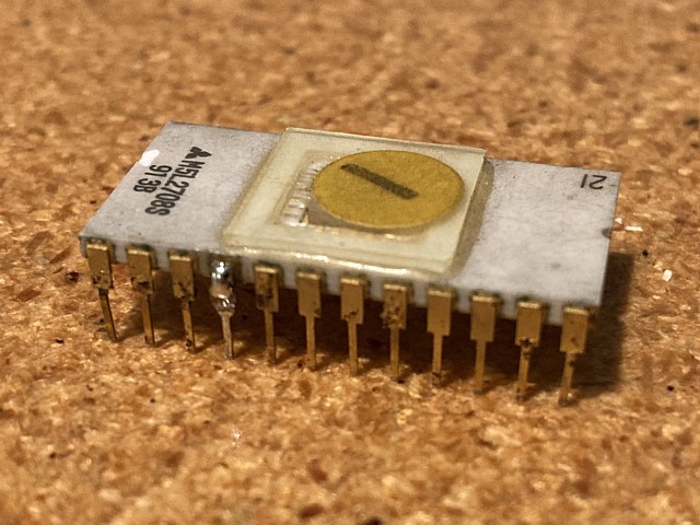
Repairing the broken pin by soldering on a spare pin cut from a faulty IC, the EPROM verifies correctly when checked with my EPROM programmer. Although the original pins are gold plated, moisture does attack any exposed areas and the steel pins eventually rust away from the inside. In this photo several pins are showing signs of deterioration but still intact for the moment.
I'm making an attempt to repair the original game PCB from an Omori Shuttle Invader machine. I already have another, working Shuttle Invader PCB to install into the machine but I'd like to repair this one if possible to have a working spare. I'd also prefer to use this one initially to test out the rest of the machine before installing my known good PCB.
This one is in pretty poor shape with several areas having messy traces of previous repairs, it could be someone has already tried to resolve the most recent issue and may even have made it worse.
So far I've replaced a couple of faulty ICs to correct the sync timing and CPU reset signals as well as resolving a couple of broken connections due to corrosion on the PCB tracks and IC pins.
Having done that the address signals from the CPU and select signals via address decoding now appear to be reaching the EPROMs and their data returning via the bidirectional buffers in positions 15F and 16F.
Now looking at the signals around the RAM there are issues in this area as well. That's not surprising - on initial inspection I had noted some obvious repair attempts with a number of broken tracks jumpered and generally messy soldering which suggests all of the RAM ICs may have been desoldered and tested or replaced at some stage.
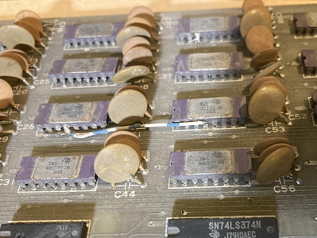
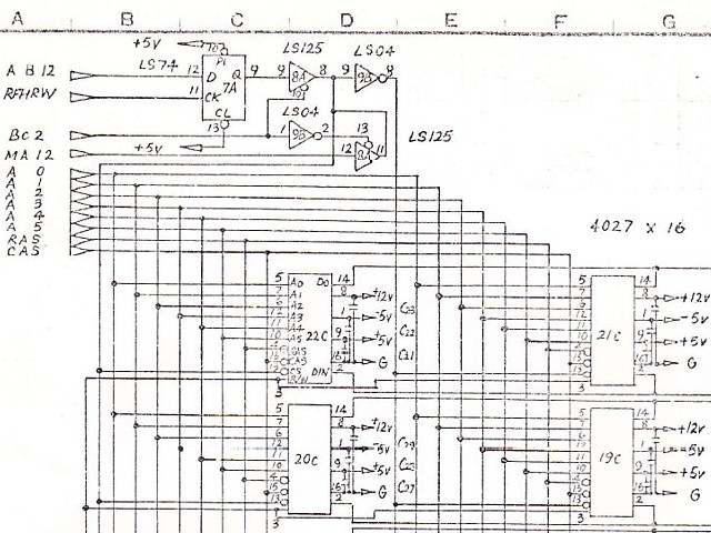
The dynamic RAM comprises 16 ICs, type 4027 each having a capacity of only 4k x 1 bit, making a total of 8k Bytes. Address lines are combined into rows and columns so there are row and column address strobe signals in addition to select and read /write controls as well as separate input and output pins for the single data bit from each IC.
Checking their signal activity the first obvious problem is the row address strobe /RAS has an invalid, low signal level. This comes from the 74LS08 in position 20B so replacing that IC and retesting, unfortunately has not resolved the issue. The most likely cause seems to be a short circuit track or perhaps one of the ICs has a shorted input.
At this point it seems prudent to test all of the connections to the RAM for continuity as well as checking for shorts between adjacent tracks. The majority of signals to the RAM are bussed across all 16 positions, the select lines into two banks of 8 ICs and the data input and output pins grouped into pairs.
So, beginning with pin 1 of the 4027 in position 19C, testing the continuity to pin 1 of each other RAM IC and so forth, all of the expected connections seem to be present. I did note some of the interconnecting tracks and pads had been broken or lifted when the ICs must have been removed for testing, then repaired with jumper wires soldered in place to bridge the gaps.
Next testing for shorts from pin 1 of the first IC to each other pin and so on, there is a problem. Pin 3 (R /W) is shorted to pin 4 (/RAS), as these signals are bussed across all RAM ICs the short could be anywhere within the RAM section on either side of the PCB.
Fortunately turning the board over and inspecting closely I located the solder bridge which appears to be the result of a slip of the soldering iron when the previous repairer was removing or replacing ICs. As the PCB has no solder mask on either side it is easy to accidentally bridge two adjacent tracks, in this case the solder 'dag' spans three tracks shorting pins 3, 4 and 13 (/CS).
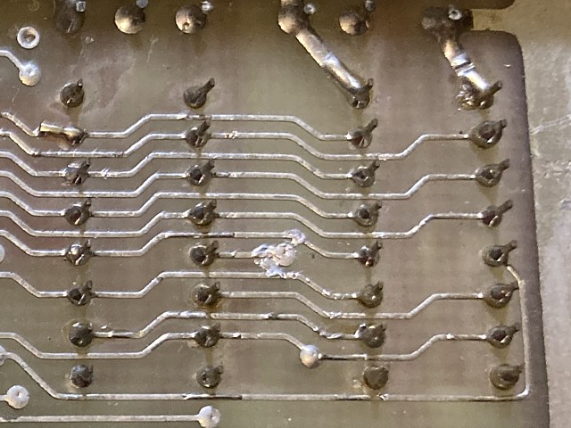
That little mistake had apparently gone unnoticed at the time and from that point on the previous repair attempt was doomed. Without correcting that short any further components tested or replaced would have failed to make any significant improvement.
Having taken a high res. photo of the affected area to illustrate that particular fault I can't help noticing a number of messy solder joints in that section of the PCB. Using the photo as a guide I've located a second solder bridge and, taking a close up photo from a different angle it can be seen clearly below:
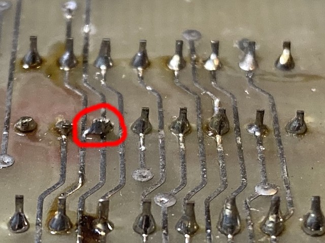
That solder bridge connects pin 2 (Data in) to pin 14 (Data out) and would cause a single bit error across every RAM address. This would have more likely been diagnosed as a RAM failure than a PCB short and it remains to be seen whether any or all of the actual ICs have survived these multiple shorted inputs and outputs.
Powering the board on again - after correcting those two solder bridges - rechecking the signals around the RAM ICs the /RAS and /CAS signals now both appear to be present and correct. The Read /Write signal however is sitting between 1 and 2 Volts and just seems to contain a bit of noise so there is most likely some further damage caused by the previously shorted tracks.
Tracing the R/W signal back to the 74LS00 in position 21B, replacing that IC cures the incorrect level but there is still no activity on its output pin 6 due to its input pin 4 remining Low. That turns out to be due to a faulty 74LS74 in position 22B, replacing that IC as well (having added sockets for both) restores the activity and at last we have some meaningful video on screen.
That may not seem like much of an improvement but the random garbage has been cleared away and there is a recognisable zero character in the score area to the right of picture. The zero looks correct so at least some of the video RAM must be OK but the other half of screen has some corrupted character near the centre and a flashing bar in the laser base area, perhaps one bank of video RAM still has errors.
- I'm not worried about the washed out appearance and lack of contrast, that is just becaause this PCB is configured to be used with the colour overlay PCB - its monochrome video output has an increased level of sync and reduced video level. Once I have this PCB to the point where the game appears to run I will connect up and test the colour overlay PCB using my NEC monitor's RGB input.
I'm returning to this Omori Shuttle Invader PCB repair following a pause while I completed some other, more pressing repairs and projects. To date I've found and corrected a number of issues with faulty ICs, corroded tracks and broken IC legs as well as shorted tracks caused by some previous, failed repair attempt by persons unknown. As I left it there were now some recognisable characters visible on screen but the program was still not running correctly, hinting at some remaining data or memory issues.
The three banks of memory on the PCB are 8kBytes of program ROM (only 6kBytes are populated for Shuttle Invader), 8kBytes of dynamic RAM and 1kByte of static RAM. Although I've removed and verified the six 2708 EPROMs I'm not certain the program instructions read from them are reaching the CPU without error, the waveforms seen at the data buffers for this section show some invalid, low level signals.
It may be these intermediate levels are only seen during bus idle time when no devices are selected but they could be due to a bus conflict where two devices are incorrectly selected at the same time, their outputs clashing and causing data errors with invalid levels. Comparing the timing of the select signals for the EPROMs and static RAM, which both appear on this section of the data bus along with the /DIEN signal which controls the direction of the data buffers I can't see any conflicts so for the moment I'll move on and look for problems elsewhere.
The dynamic RAM comprises two banks of 4kByte, totalling 8kByte. The first 6kBytes are used for the video bitmap, the remaining 2kBytes presumably used as working RAM for the program in addition to the 1kByte of static RAM. Dynamic RAM was often used in video circuits of the era as it was less expensive than static RAM. The main drawback of dynamic RAM was the need for a refresh process to maintain its data but a video circuit which reads the data in a continuous cycle performs that function without the need for additional circuitry.
To see recognisable characters on screen the video area of RAM must be working to some extent, being written by the CPU and read out by the video circuit. Any persistent bit errors would show as lines or dots on screen. Double checking the timing signals which are used within the video circuit to read the video RAM data and create the video signal, I notice that signal MA12 is not active. This is the highest level address signal used within the dynamic RAM area so effectively switches between the two 4kByte RAM banks as the video data is being read out.
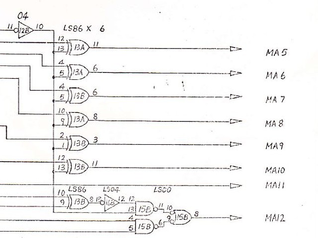
That problem turns out to be due to a faulty 74LS00 in position 15B so removing, socketing and replacing that I'm expecting a dramatic improvement to the image on screen. Powering on again I'm surprised to see the image looks much worse! Two thirds of the screen area now just contains a sort of dot pattern. Even though it looks worse it was a step in the right direction as it turns out one half of the dynamic RAM was never being accessed at all, the data being written to the upper bank then overwritten by other data.
So now, we're reading the full RAM address range but the first bank is still not being written to. Tracing the select signal back to address AB12, the 74LS74 latch in position 7A is also faulty. Replacing that, adding a socket corrects the addressing issue and the screen has improved but the program is still not running correctly. This seems like a large number of simultaneous faults and so many faulty ICs but several of these issues were probably caused by the previous 'repairer' who shorted a number of tracks on the PCB, no doubt causing additional component failures on top of whatever issue they were originally attempting to fix.
Assuming that the dynamic RAM is now working for the most part (judging by the recognisable characters on screen) there still remains the issue of the 1kByte static RAM which may be faulty and could be causing the program to stall at an early stage. The problem here is there's not much activity in that area to observe so it's unclear whether the program is failing because of errors in the static RAM area or for some other reason, before the static RAM is even accessed.
Neither of the 2114 RAM ICs are socketed so it would be preferable to test them somehow without desoldering or having to substitute known good RAM ICs. At this stage there are so many unknowns it seems worthwhile to develop a small test program to substitute into the boot ROM area which performs some known tasks and tests the dynamic and static RAM for errors from the CPUs point of view. Writing programs in assembly language is not my forte but a simple program loop to write, read and check each memory location can be incredibly helpful in situations such as this.
My first attempt at a program to excercise the hardware on an arcade PCB was for the 6502 CPU in Missile Command, that program did little more than read every address from 0000 to 7fff in a continuous loop. It did nothing with the data read, what it did achieve was to create some predictable activity on the CPU address bus which could be viewed on an oscilloscope enabling hardware faults to be easily traced.
Missile Command already incorporates some diagnostic and memory testing routines so once initial addressing issues were sorted the inbuilt diagnostic software could be accessed and there was no need to develop the 'reading every address' program beyond that purpose.
My next attempt at a test ROM, for the z80 CPU in Exerion by Jaleco was more ambitious. Exerion included no diagnostic software so I wrote a test routine which checked three areas of RAM, outputting results to that PCBs text layer, followed by a version of the 'reading every address' loop for good measure which also placed a character on screen for every address read to indicate continuing activity.
Exerion Test ROM, 2021 - running in MAME
For Shuttle Invader which is an earlier game using an 8080 CPU with a limited instruction set and only bitmap graphics ability achieving the same goal will be more challenging. Compared to the z80 instruction set, the 8080 has no extended instructions for data fill or individual bit operations. The original EPROMs on the Shuttle Invader PCB are 2708s with only 1kByte of storage so the entire program including any graphics should ideally be written to fit within a single EPROM.
For a RAM testing program there is another limitation, the RAM itself can not be relied upon for the program to run. The entire program should only make use of the CPUs internal registers and the 'boot ROM' location for the program itself. That means no subroutines can be called or any data pushed onto the stack for temporary storage as these operations require a known good area of RAM to be set aside.
The program I've written begins by filling the dynamic RAM area with data, beginning with all zeros then reading each address back and checking for errors. If all good it increments the data and repeats the process for every data value from 00 to FF. As most of the DRAM is video memory the resulting patterns should be visible on screen as the test progresses. At the beginning of each test loop a brief, low pitch tone should also be heard.
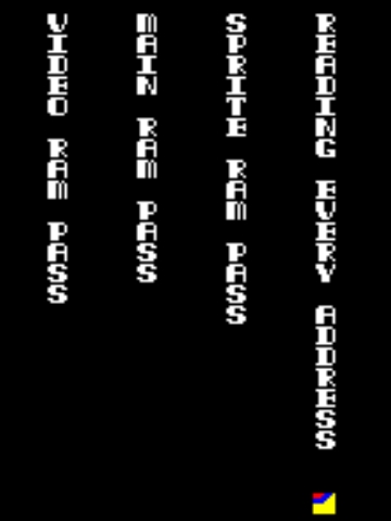
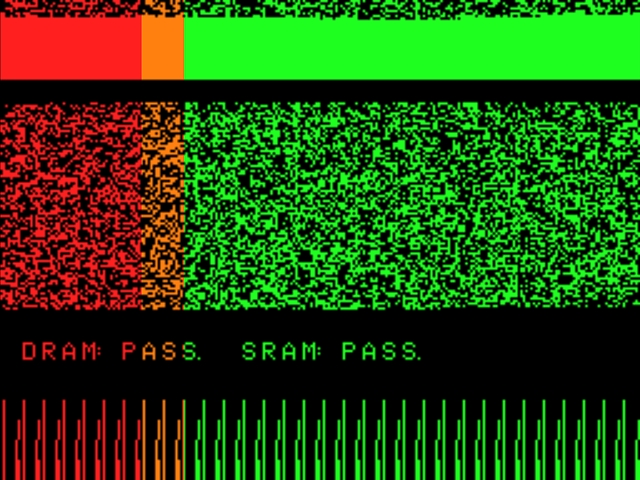
If that completes correctly it does two more passes where the address of each memory location is written as data, first using the high order address byte of each memory location then the low order byte. The purpose of this last step is to identify any addressing errors where data may be written to the wrong memory location then overwritten by other data. If there are no errors a 'DRAM: PASS." graphic message is transferred to the video memory and a similar process commences for the static RAM area.
As the static RAM is being read, each byte read is also written to an area within the video RAM area so the patterns read back from static RAM can be viewed on screen. If these tests pass a "SRAM: PASS." graphic message displays that result and the program moves on to a continuous 'reading every address' loop, also writing the data read to an area within the video memory so the activity can be viewed on screen.
At any point during the RAM testing if there is a read error a high pitch tone sounds and the program continuously rewrites and re reads that memory location, announcing the result with a low or high pitch tone each time. Repeating the write and read of that particular memory address allows the problem area to be identified in circuit using an oscilloscope or logic probe. In the latest version of the test ROM the address, data written and data read back from that location are decoded and displayed on screen as a graphic message allowing a faulty RAM IC to be identified directly.
So having completed the memory test program, confirming its operation within MAME it's time to run it on the actual hardware and see what it finds. Programming a spare EPROM and substituting it into the boot ROM position 1, powering on there is a low tone immediately followed by a high tone and an error is indicated at the very beginning of DRAM with data 00 written and 01 read back.
This would correspond with the 4027 RAM in position 21C. Anticipating some RAM issues I had recently ordered a couple of 4027 ICs from a local supplier which have already arrived so, desoldering the suspect IC and adding a socket then installing the replacement we're ready to re test. Powering on again, this time the test routine continues for a minute or so and the 'DRAM: PASS.' message appears. I'd call that a success! the memory test has correctly pinpointed the single IC from a group of 16 which had some bit errors.
Moving on to the static RAM tests and once again, failing almost immediately the screen indicates an error near the beginning of the static RAM address range with data 00 written and 02 read back. That error is within the lower 4 data bits, corresponding to the 2114 RAM in position 15C. Removing, socketing and replacing that IC and powering on again the test proceeds just a little further and another error is indicated. This time the data written is 10 and read back as 00 so that corresponds to the other 2114 in position 16C. So it turns out both of the 2114 static RAM ICs were faulty.
As it happened, I could have just removed and replaced both of the static RAM ICs on suspicion and would have been right in this case but being able to test them without removing is by far a better method. In the case of the dynamic RAM, the previous repairer appears to have removed and resoldered every IC, failing to locate one faulty component and creating a number of additional faults in the process. With the help of my RAM test the single remaining fault was identified and faulty IC replaced without disturbing any of the other components.
With RAM tests now passing it's time to refit the original EPROM and see if the program runs. Powering on again we have a working attract screen, the game coins up and plays, sounds appear to be working as well. Fantastic! The game runs at last but there are still some issues, after a while alternate strips of the video image begin to disappear but the game seems to still be playing correctly so that's probably an issue in the video output area rather than a more serious program error. We'll look into that next.
The Shuttle Invader PCB is running now with one graphics issue, alternate rows of the image are cutting out as the PCB warms up. This doesn't seem to affect the program flow or game play so would most likely be a fault in the video output section of the PCB. The video data is loaded one byte at a time into a pair of 74LS194 4 bit shift registers and then shifted out as video, each bit representing one pixel. A pair of mode control signals allow the shift direction to be reversed during flip screen operation.
Checking the outputs of the shift registers, the one in position 18C definitely appears faulty. This is consistent with the symptoms, where one half of each character is missing so I'm ordering a couple of replacement ICs from a local supplier. Once those have arrived, removing and replacing that IC fixes the problem. We now have a working display.
The next step is to set up and test the colour overlay PCB which converts the black and white image to an RGB colour signal, to drive the 14 inch Toei colour monitor fitted to the machine. Video and timing signals from the game PCB are fed to the colour board via a 16 way ribbon cable plugged into standard DIL IC sockets at either end. This was a common interconnection standard at the time but rarely seen in more modern equipment.
A couple of the pins of the DIL header plug at one end were broken off so I've made up a complete replacement cable. That was one of the failings of this type of interconnection, the header pins which were no stronger than IC legs were quite fragile and easily broken if the cable was unplugged and left exposed. There was also nothing to prevent the header from being plugged in backwards apart from the pin 1 marking on the cable.
The +5V and +12V supplies to the PCB and RGB outputs are connected within the machine via a double sided 22 way edge connector but also appear on a second, 16 way DIL IC socket so for testing purposes I'm making up a cable to connect via another DIL header plug, interfacing with the RGB inputs of my NEC TV monitor. The sync signal comes directly from the game PCB, using the original monochrome composite video output.
I've set up the colour overlay PCB from the Omori Shuttle Invader machine on the test bench along with the now working game PCB and it's time to see the game in colour for the first time. Expectations are high so, switching to my test bench monitor's RGB input and powering on, here's what we get:
OK, so slightly less than expected - there seem to be two issues here. Firstly everything is red and apart from that some sections of the image are missing entirely. There are two possible reasons for the colour issue, both green and blue outputs could have failed or the colour PCB may be stuck in the 'laser base explosion' condition.
Normally only seen as a momentary flash of red, when the player's laser / missile base is hit an explosion sound is triggered and a signal /outFCH is pulsed which changes the screen colour to red momentarily. The duration of the red flash is set by a 74121 monostable (one shot) IC in position 2C on the colour PCB, triggered by the /outFCH signal via a 74LS04 inverter.
Checking those signals with the oscilloscope it appears the /outFCH signal is hovering at around 2 Volts with some glitchy noise as well. At the inverter output that becomes a repetitive pulse which continuously retriggers the monostable IC, resulting in the consistently red image. That issue appears to originate from the game PCB so, temporarily disconnecting the ribbon cable from the colour PCB and looking at the /outFCH signal on pin 9 of the 74LS155 in position 5D this is what we see:
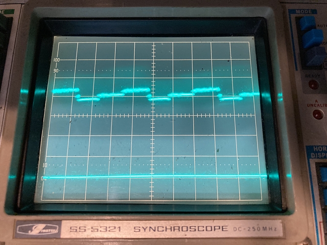
That's not as expected and the Voltage, between 0 and about 3V obviously not a valid TTL signal. The output should just show as a logic high, briefly pulsing low each time the player base is hit so the 74LS155 is definitely faulty. Fortunately I have some spares on hand along with 16 pin sockets so removing that IC and replacing, setting up again we have some improvement to the image on screen.
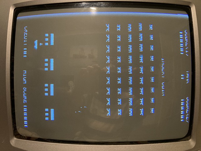
At least we now have some correct colours but there appears to be a more serious issue as sections of the image are missing. In the Player 1 view the invaders are completely invisible at first, appearing intermittently as they advance while other details such as the scores and barriers are only partially shown. It seems that alternate rows of the image are blank.
That would suggest a problem with the bipolar PROM which is used as a lookup table to define the colour for each section of the image. The PROM is a type 82S129 (or 74S287) and has a capacity of 256 x 4bits i.e. 256 nibbles or 1k bits total. In this application only 3 of the 4 data bits are used, one for each colour Red, Green and Blue.
There are 8 address lines, the lower 5 are connected to horizontal timing signals MA 0 to MA 4, effectively dividing the screen area into 32 character rows. The other 3 address inputs select alternate regions of the ROM area for flip screen, laser base explosion and non active video (blanking) areas. A PROM can not be erased and reprogrammed so will require replacement in the case of any error or fault.
The first step is to read and verify the PROM contents against the known file referred to within MAME for Shuttle Invader. Although I don't have a suitable programmer for these devices (and no modern programmers support them) they are not too difficult to read using my existing EPROM programmer and a custom adaptor to match the pinout of the PROM to that of a 2716 EPROM.
The adaptor in the foreground is used for 256 x 4 bit PROMs such as the 82S129 while the other suits 32 Byte types. In this case 256 bytes are read and stored as a binary file, the upper 4 bits always being zero. So, reading the PROM from position 2B of the colour PCB and verifying it against the known 82s129.2b file there are some differences and the two files do not match.
We can look at the contents of the two files graphically using the program 'YY-CHR' - in the known file (left picture), there is a simple pattern which represents the colours enabled for each segment of the video image. The areas in which only a single bit is selected, appearing here as a thin line would be the red screen which flashes up when the player missile base is hit.
The image on the right shows the data read from the PROM on the colour PCB. It seems the content would have been the same except alternate data locations now read as all zeros. This seems more likely due to some internal addressing issue within the PROM rather than a fault in the fusible link array but either way the faulty PROM can not be reprogrammed and needs replacement.
|
 |
To replace a faulty PROM there are three requirements; a blank PROM of the same type or equivalent, a suitable programmer with correct adapter for that particular component and the correct data file to program into the blank PROM. I'm confident that the reference file I've used to verify the original PROM is correct but don't have a blank PROM or suitable programmer to create the replacement.
The main concern with purchasing a small quantity of blank PROMs is that many items which are listed for sale online as new parts actually turn out to be second hand parts reclaimed from old PCBs. In the case of bipolar PROMs any second hand item will be useless, having already been programmed and impossible to erase and reprogram.
As for programming, there are some older type EPROM programmers with suitable adapters to program bipolar PROMs but these are now extremely sought after and seldom come up for sale. It may be possible to build a homebrew programmer for a specific PROM type but in order to reliably program these devices there are very precise conditions of pulse timing and current required.
A few 'hacks' which I've read about to achieve this would be very hit and miss at best, with a high probability of programming failure and wasted devices as a result.
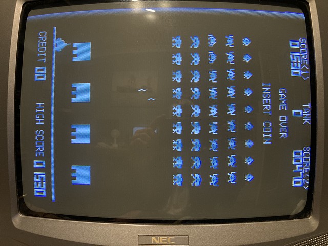
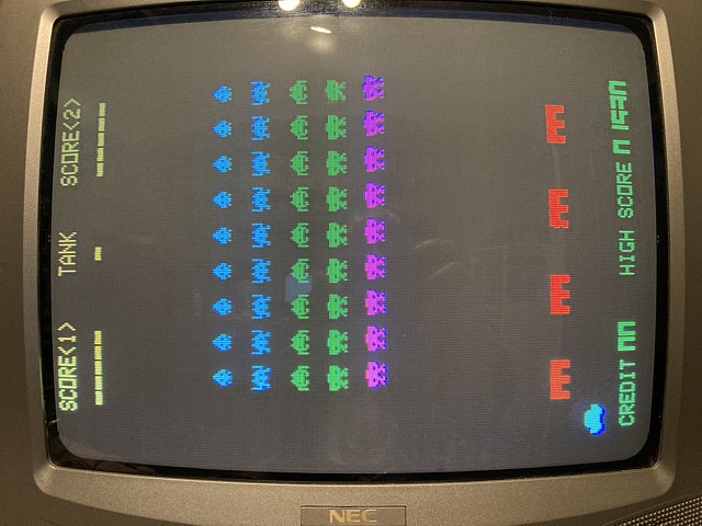
Fortunately I've found someone who can not only supply a blank PROM but also program it with the data file I already have, saving me the extra trouble and expense of attempting to program it myself. Within a few days the newly programmed PROM has arrived by post so fitting it to the colour PCB and testing; the colours, flip screen and red flashing now all appear perfect!
The Shuttle Invader PCB is working well and colour video output looks good so the board repairs now seem complete. There's one modification I'd like to add while I still have them on the bench, that is to also run Omori's Sky Love game. I have already done a similar modification to my first Shuttle Invader PCB so this will be similar except for the type of EPROM used.
Shuttle Invader originally uses 6 x 2708 EPROM totalling 6k Bytes and Sky Love requires 8k Bytes. My previous modification used 8 x 2716 EPROM to contain the two ROMsets, in this instance I'll adapt one of the currently unused PCB ROM spaces to fit a single 27128 EPROM which will accommodate both entire ROMsets.
Here I've desoldered the PCB pads to install an IC socket in the unused ROM 6, position 11E on the PCB. The 27128 is mostly pin compatible with the 2708 but, having a 28 pin package does require an additional 4 through holes as well as a few track alterations. To make room I've removed C130 which is a 0.1uF ceramic capacitor used as a bypass to reduce high frequency noise, between +5V and ground.
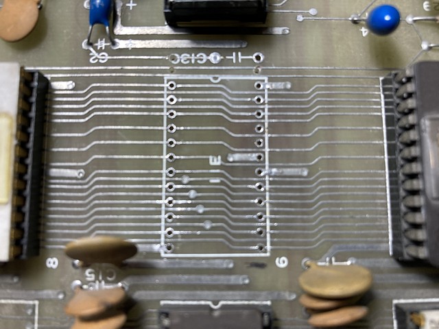
I'll relocate C130 to a nearby pair of through holes which connect to the same points, using a monolithic capacitor of the same value which is physically smaller. I've drilled 3 additional, 1mm holes for the 28 pin IC socket - the existing PCB tracks which pass through those points need to be cut either side of the new holes and bypassed with wire. I also need to cut those power rails from pins 19 and 24, before installing the 28 pin socket.
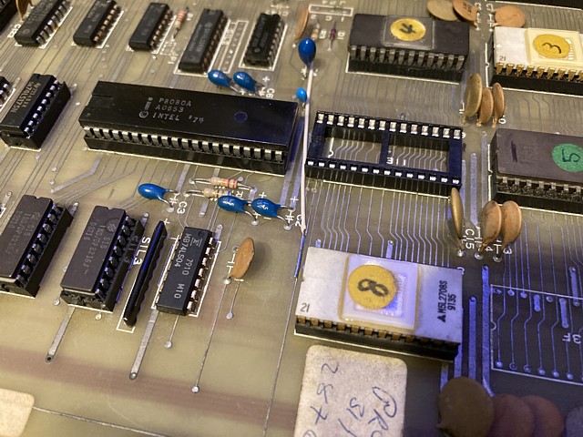
Tracks cut, 28 pin IC socket installed and wire added. The wire restores the connection from CN2 to the reset input of the 8224 clock / timing generator IC in position 9D. I've also installed the smaller monolithic capacitor as replacement for C130 to the nearby through holes which connect to +5V and ground rails.
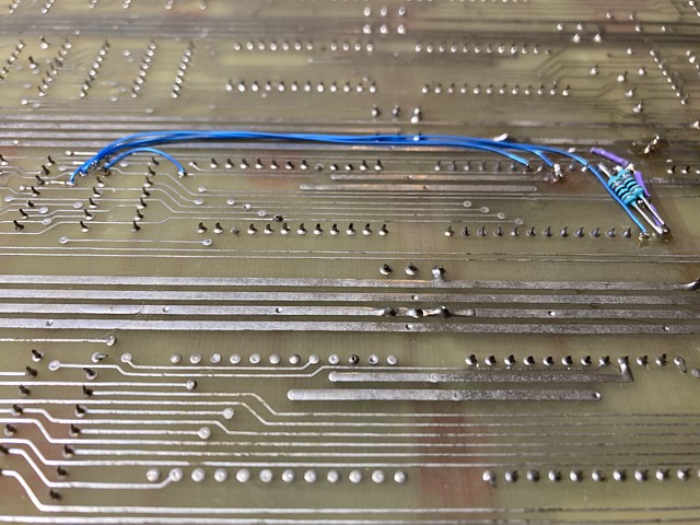
On the solder side the blue wires carry the /ROM ADDR select signal and additional address lines A10, A11 and A12 to the 27128. 10k Ohm pullup resistors added from +5V to /PGM and A13. The A13 input will be used as the bank select signal, a small DIP switch to ground will select the Sky Love game.
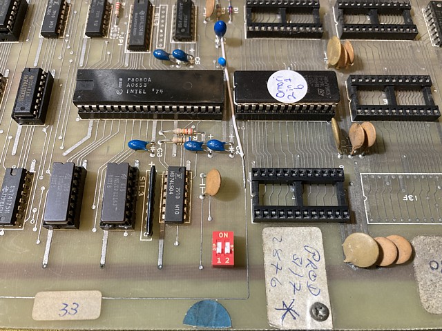
DIP switch added, 2 in 1 EPROM programmed and installed, original 2708 EPROMs removed. The modification could easily be reconfigured to support a 27256 EPROM, DIP switch position 2 would then be used to select additional, diagnostic software. The PCB will also still work correctly with the new EPROM removed and original 2708 EPROMS refitted.
So I now have two working Shuttle Invader PCBs, both also capable of running Omori's obscure Sky Love game. The next step is to get back to the machine, test the monitor and power supply which both appear to be working to some extent and possibly overhaul those if required before refitting the game and colour PCBs and tidying up, checking controls etc.
To be continued...
Web Resources (External Links) -
Omori Shuttle Invader and Sky Love running on a Shuttle Invader PCB - Youtube
Shuttle Invader Part II Flyer - flyerfever.com
Sky Love Flyer - flyerfever.com - Colour version
Sky Love Flyer 2 - flyerfever.com - Note alternate colours shown on screenshot.
All images and text on this website are Copyright.
Contact: jbtech at telstra dot com