Nintendo / Fortrek Space Demon PCB set
I have another Arcade PCB set on the bench for repair, this one is Space Demon - Made by Nintendo, copyright Fortrek 1980.
This game is obviously based on Space Firebird hardware but was apparently developed by Fortrek, an obscure name with only two Nintendo based titles to their credit. The CPU and Video PCBs seem identical to Space Firebird but I understand there were some hardware changes to the ESS Sound PCB so conversion from Space Firebird to Space Demon would not just be a simple ROM swap. All three PCBs are genuine, having the FORTREK-05- prefix screen printed on them.
Why Nintendo licensed the development of a Space Firebird 'sequel' to an outside entity is a bit of a mystery. I'm inclined to wonder if it was a similar situation to the development of Ms. Pacman in the U.S. where an unauthorised hack of the original Namco / Midway Pacman game eventually became its licensed successor. By the time Space Demon was being developed Nintendo would already have been busy putting the finishing touches on their soon to be released 'stubborn ape' game which, very loosely translated became Donkey Kong.
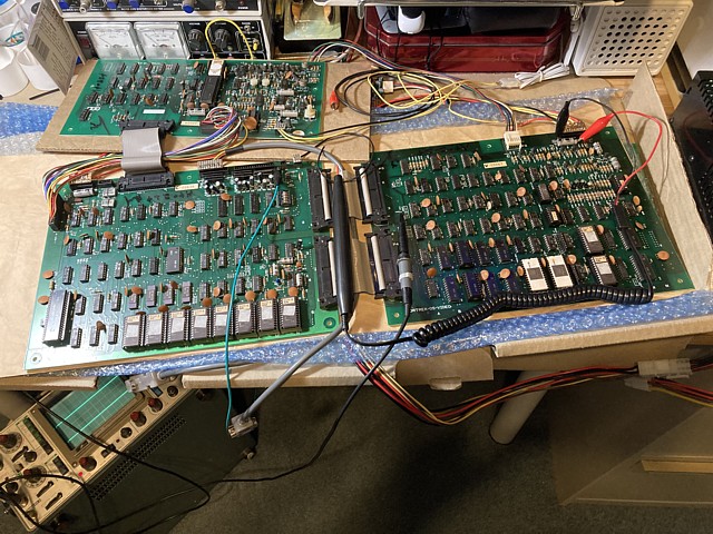
Setting up on the bench as per my previous Space Firebird repair, in this case the symptoms were reportedly a burst of sound followed by some rolling characters on screen then nothing. Powering on, the result is exactly that. I did notice that the characters on screen looked like numbers and text, they were rolling vertically on my test bench TV monitor which has standard 'horizontal' orientation.
So the first course of action will be to check the vertical timing and sync signals generated on the CPU PCB. I haven't found any circuit diagrams specific to Space Demon so will be referring to the Space Firebird version and note any differences encountered. As with many arcade games the main clock frequency is progressively divided using a cascade of binary counters to generate the horizontal, then vertical timing signals.
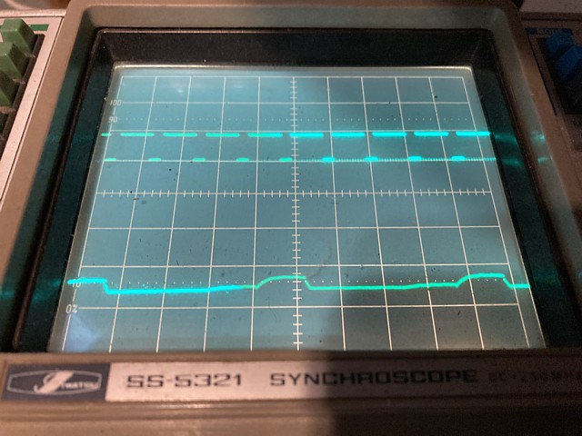
In this case the oscillator frequency is 20.160 MHz and a bank of 74LS161 counters are employed. Using the oscilloscope to check their outputs, when I work my way down to the vertical frequency signals from the 74LS161 in position 2M there are some obviously low level waveforms on its outputs.
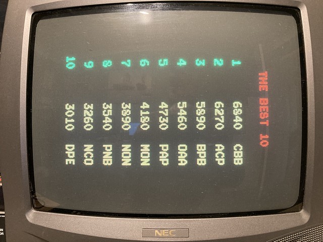
After removing that IC, fitting a new socket and installing a new replacement 74LS161 - when powered on the game springs to life!
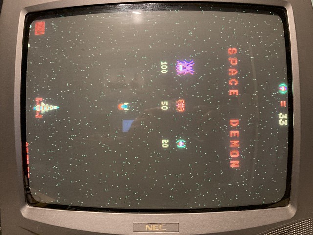
It seems too good to be true. The attract mode runs, game coins up and plays, sounds seem correct. But I can't help noticing a distinct lack of blue in any of the images. Admittedly the colours chosen by Fortrek seem to favour red, green and yellow but comparing the player and enemy characters to those in the MAME emulation of Space Demon there should be some magenta and cyan (purple and light blue) details here and there.
So, comparing the red, green and blue output signals at TP 1, 2 and 3 on the video PCB, there is a definite problem. The blue signal is present but its amplitude is almost nonexistent compared to red and green. That strikes me as a possible analog problem in the video output stage but, tracing back to the previous stage where outputs from the main video and starfield signals are combined there is a high DC content, the blue component from the starfield area being stuck in a high state.
The starfield signals arriving at the video PCB are inverted by the 74LS368 in position 1A so the signal in question, 'Ba' which originates from the ESS sound PCB is actually stuck low. Tracing that all the way back to pin 32 on P3 of the ESS sound PCB, I'm surprised to find that PCB track is connected to ground. Now we're in uncharted territory as that does not match the circuit diagram from Space Firebird at all.
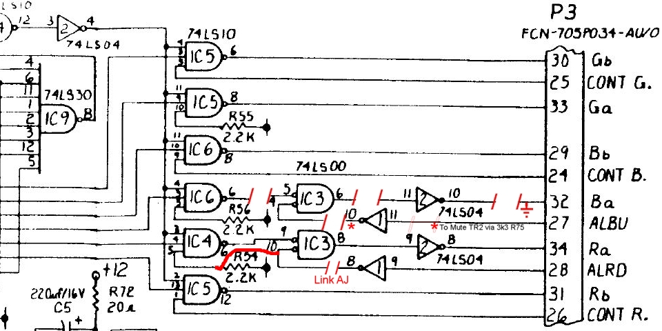
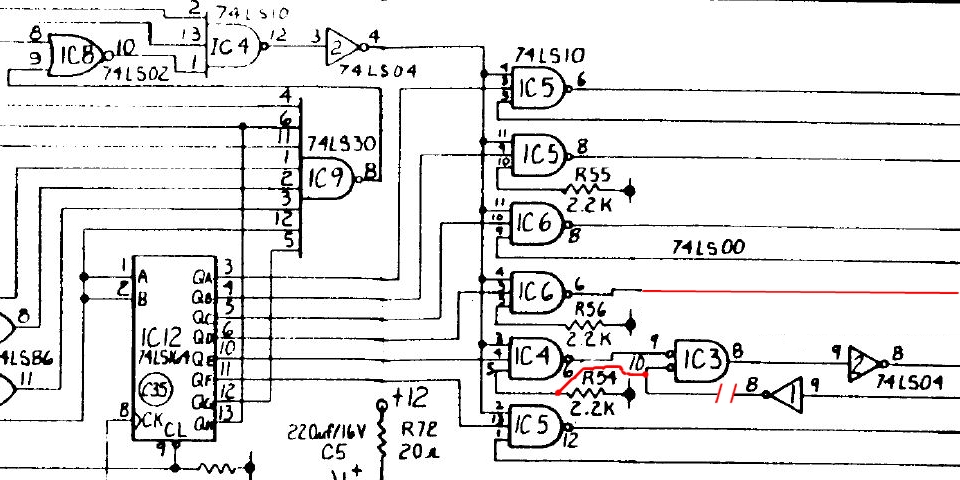
The changes in this area of the Space Demon ESS sound PCB seem to centre around two signals, ALBU and ALRD and associated components ICs 1, 2 and 3. In Space Firebird these would cause the starfield layer to flash red or blue when pulsed. I'm not sure if the ALBU signal was ever used in that game but ALRD causes a red flash to the screen when the player ship is hit.
In Space Demon the inverted ALBU signal seems to have been repurposed to drive the base of mute circuit transistor Tr2 via a 3k3 resistor, R75. I think this may be why in MAME the background turns blue during play whereas that signal should instead unmute the 7910 multi-melody IC31.
Meanwhile the ALRD signal now connects from IC1 to IC3 via a link AJ which is left open circuit. IC3 pin 10 also connects to IC4 pin 5 which initially seemed like an error in the PCB layout but I now suspect it was piggybacked onto pullup resistor R54 deliberately to prevent it from being left floating when link AJ is open.
The remaining gates of ICs 1, 2 and 3 have been left without connection and IC 6 pin 6 which carries the 'Ba' signal goes nowhere (I even removed the IC from the PCB to double check the traces on the component side, also finding that pin 5 was not connected, R56 omitted entirely). Pin 32 of P3 has been connected to ground which I'm certain was in error, the 'Ba' signal from IC6/6 should connect there instead.
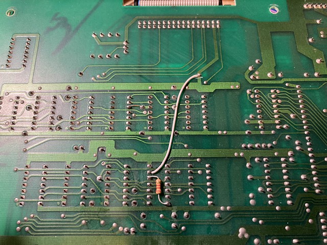
I should mention the ESS sound PCB in this case is a very early version having a serial number within the first 30 PCBs produced so this may have been corrected in a later revision. So, cutting the track from P3 pin 32 away from ground and instead adding a wire link from IC6/6 to P3/32 resolves the 'Ba' signal issue. I can only assume it was a prototype or early release oversight on this particular PCB.
Having done that the game now plays correctly, the player ship and enemy sprites looking correct with cyan and magenta details in addition to their still predominantly red, green and yellow colouring.
The Nintendo / Fortrek Space Demon PCB set appeared to be working correctly, having found and corrected two faults thus far. The first and most obvious was a problem with the vertical timing and sync signals which prevented the game from running at all.
The secondary issue which turned out to be an early revision or prototype error on the ESS sound PCB, caused the blue signal from the starfield generator to be stuck in a high state. That in turn caused some clipping in the blue video output stage, resulting in an overall decrease in the blue content of the objects in the foreground layer.
Resolving that issue corrected the lack of blue which was most noticeable in the player and enemy sprites on screen. Meanwhile the starfield layer appeared to be working, the coloured dots flickering in unison while scrolling in one direction towards the players ship at the bottom of screen from the players point of view.
Although the starfield did look a bit 'busy' as seen in the photo above there are very few videos or photos available of genuine, working Space Demon games to compare to and its emulation in MAME is not an accurate guide in this case either. So the repaired PCBs were believed to be fully working, packed up and returned to their owner.
Unfortunately upon arrival the starfield had an obvious fault with many more, high intensity dots flashing on and off in random patterns and appearing to scroll in multiple directions. In addition, one of the original Nintendo linear power supply regulator modules which I had previously repaired was now reportedly overheating.
This was very disappointing, perhaps the power supply had developed a fault and damaged the newly repaired PCB or the PCB set had developed a new fault which caused the power supply to overheat. Perhaps there was a pre existing fault in the starfield section of the game PCBs which had worsened. The only solution would be to get the game and power supply PCBs back and test them once again.
Once the PCBs had returned, setting them up on the bench and and testing; initially the starfield looks good but as the board warms up some spurious dots begin to appear giving the starfield a very cluttered appearance. There is definitely a fault which was not apparent before and does seem to be somewhat intermittent.
Checking the starfield signals on the ESS sound PCB and tracing back from the outputs, there is a problem with what appears to be a key signal which originates from IC9, pin 8. That output is stuck at about 2V which is not a valid TTL level and does not seem to contain any active data. This is right at the threshold between a logic Low or High and could either cause the starfield outputs to become muted or present when not intended.
So replacing IC9 also adding a socket, cures that problem and the starfield now appears much more as expected. Just to be sure I'll check each of the colour signals at their respective outputs to make sure all are now active. There are two bits for each colour which would allow 64 colour combinations with potentially subtle variations compared to slightly earlier games which most likely had an 8 colour starfield palette.
At this stage the colour signals are inverted so normally high for a black background with very brief low going pulses to place a small dot on screen to represent a distant star. So brief, I'm having trouble viewing them clearly on my oscilloscope though the trigger circuit does indicate their presence. My analog oscilloscope having no storage ability is better suited to displaying signals with a regular repetition rate.
Switching to my logic probe, checking the green outputs at IC5, pins 6 and 8 also the blue outputs at IC6 pins 8 and 6 all are showing a high signal with low going pulses. So far, so good. Looking at the red signal from IC4 pin 6 I can't find a pulse (oh dear!) so I try replacing that IC. That seems to restore the activity from IC4 and also IC3 pin 8 but the final output from IC2 pin 8 also shows a high output and registers no activity.
After replacing IC2 that issue seems to remain. There is activity on its input but its output seems to remain high, if there is a pulse it is either so brief or not reaching a logic low level to register on my logic probe. One possible cause of that issue would be the 74LS368 buffer at the input to the Video PCB, if this is faulty it could be loading the signals from the ESS sound PCB so I will try replacing that. I don't have that component on hand at present so will add a couple to my next parts order.
Meanwhile I'll put the Space Demon PCBs to one side and move on to re testing the power supply regulator module. A quick initial check shows all of the output Voltages are correct, regulators appear to be working so I will give the module a more extensive test under load conditions and eventually test the repaired game PCBs and power supply module together.
I've been waiting on a small parts order to complete repairs to the Nintendo / Fortrek Space Demon PCB set. Now the parts have arrived I'll replace the 74LS368 inverting buffer in position 1A on the video PCB. Having done that and re-testing the starfield colour signals which originate from the ESS sound PCB all are showing regular activity.
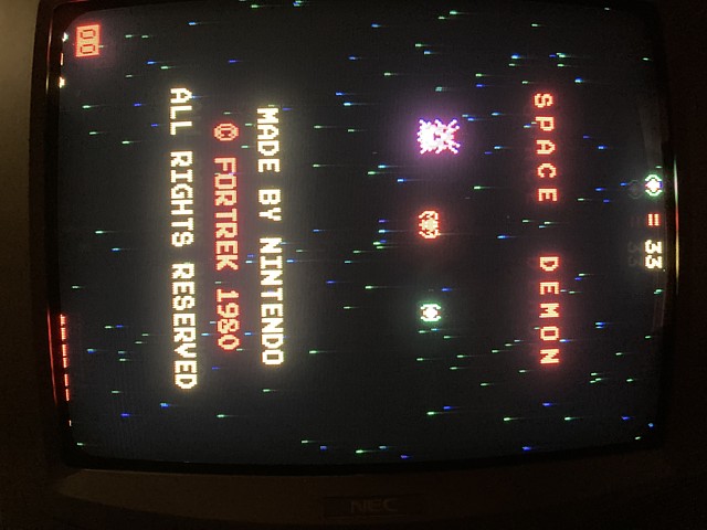
Looking at the image on screen the starfield now appears to be correct with red, green and blue dots scrolling and flickering in unison. Comparing the screen shot below to the previous one above it appears the starfield fault was already present but may have been intermittent. So that's three separate issues with this PCB set which have now been corrected.
Meanwhile checking the power supply regulator module did reveal another problem, this time with the original 2SA1012 series pass transistor for the +5V rail. Although regulating correctly with a moderate load the transistor was breaking down at higher current or temperature.
Removing the transistor and testing with a multimeter did show some continuity from Emitter to Collector which is abnormal so I've replaced that transistor as well as the same component used for the +12V rail, both now substituted with the higher rated MJE2955 type.
That done and re-testing all of the power supply Voltages were present and stable under load so the final check was to run the actual Space Demon PCB set from the repaired power supply module using the original 9pin and 10pin connecting cables from the machine.
Powering up once again, this time using the repaired Nintendo power supply module the Space Demon PCB set ran correctly; graphics, soud and game controls all working as expected. I did note with the actual game PCBs connected the power supply module ran very hot especially the small aluminium heatsink for the +5V regulator.
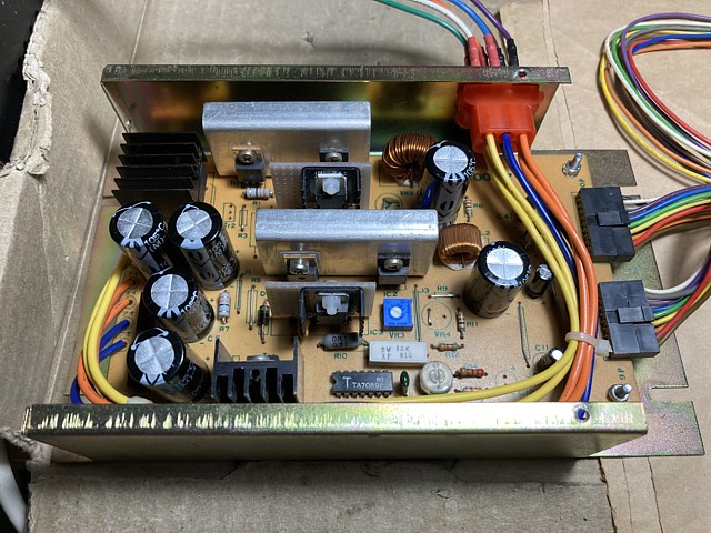
The conclusion I've reached is that the original Nintendo power supply modules had several component weaknesses as well as a serious underlying design issue, being the inadequate heat sinking for the series pass transistors. The amount of heat released by each transistor is entirely a function of the Voltage drop from input Voltage to output Voltage multiplied by the current drawn.
In the case of the +5V rail for example with a 10V AC input for a 5V DC output at a rated 3 Amps that would represent 30 Watts of input power for only 15 Watts delivered, the other 15 Watts being wasted as heat and an overall efficiency of only 50%. Put simply that means apart from its primary function as a power supply this unit performs equally well as a heater!
So the only possibilities for reducing the temperature of the power supply components would have been to avoid an excessively high input Voltage from the transformer and to use a sufficiently large heatsink to dissipate the surplus heat released.
Definitely a larger heatsink or cooling fan would have been a help but these days a better option would be to use a more efficient switchmode power supply which would generate less heat in the first place rather than struggling to get rid of surplus heat from the less efficient linear power supply.
Normally I prefer to repair and retain original components but if the machine was to be put back into continuous operation that would make a good case for a little upgrade...
footnote - A more detailed account of repairing and testing the original Nintendo power supply regulator modules can be read on the Space Firebird page.
Web Resources (External Links) -
Nintendo / Fortrek Space Demon PCB repair Take 1 - Youtube
Nintendo / Fortrek Space Demon PCB repair Take 2 - Youtube
#59 Nintendo SPACE DEMON Arcade Video Game - TNT Amusements, Youtube
Power Supply Kit (TSF-CL, TST, TWG, SDM, TUB, TSC) - MikesArcade.com
All images and text on this website are Copyright.
Contact: jbtech at telstra dot com